

Yagi antenna
Encyclopedia
Directional antenna
A directional antenna or beam antenna is an antenna which radiates greater power in one or more directions allowing for increased performance on transmit and receive and reduced interference from unwanted sources....
consisting of a driven element (typically a dipole
Dipole antenna
A dipole antenna is a radio antenna that can be made of a simple wire, with a center-fed driven element. It consists of two metal conductors of rod or wire, oriented parallel and collinear with each other , with a small space between them. The radio frequency voltage is applied to the antenna at...
or folded dipole) and additional parasitic elements (usually a so-called reflector and one or more directors). The reflector element is slightly longer (typically 5% longer) than the driven dipole, whereas the so-called directors are a little bit shorter. This design achieves a very substantial increase in the antenna's directionality
Directional antenna
A directional antenna or beam antenna is an antenna which radiates greater power in one or more directions allowing for increased performance on transmit and receive and reduced interference from unwanted sources....
and gain
Antenna gain
In electromagnetics, an antenna's power gain or simply gain is a key performance figure which combines the antenna's directivity and electrical efficiency. As a transmitting antenna, the figure describes how well the antenna converts input power into radio waves headed in a specified direction...
compared to a simple dipole.
Highly directional antennas such as the Yagi-Uda are commonly referred to as "beam antennas" due to their high gain. However the Yagi-Uda design only achieves this high gain over a rather narrow bandwidth, making it more useful for various communications bands (including amateur radio) but less suitable for traditional radio and television broadcast bands. Amateur radio
Amateur radio
Amateur radio is the use of designated radio frequency spectrum for purposes of private recreation, non-commercial exchange of messages, wireless experimentation, self-training, and emergency communication...
operators ("hams") frequently employ these for communication on HF, VHF, and UHF bands, often constructing such antennas themselves ("homebrewing
Amateur radio homebrew
-History:In the early years of amateur radio, long before factory-built gear was easily available, most hams built their own transmitting and receiving equipment, a process that came to be known as "homebrewing." In the 1930s, 40s, and 50s, hams handcrafted reasonable-quality vacuum tube-based...
"), leading to a quantity of technical papers and software. Wideband antennas used for VHF/UHF broadcast bands include the lower-gain log-periodic dipole array, which is often confused with the Yagi-Uda array due to its superficially similar appearance. That design along with other phased array
Phased array
In wave theory, a phased array is an array of antennas in which the relative phases of the respective signals feeding the antennas are varied in such a way that the effective radiation pattern of the array is reinforced in a desired direction and suppressed in undesired directions.An antenna array...
s have electrical connections on each element, whereas the Yagi-Uda design operates on the basis of electromagnetic interaction between the "parasitic" elements and the one driven (dipole) element.
The Yagi-Uda array was invented in 1926 by Shintaro Uda
Shintaro Uda
Japanese inventor. Assistant of professor Hidetsugu Yagi at Tohoku University, where they invented the Yagi-Uda antenna in 1926. In February 1926, Yagi and Uda published their first report on the wave projector antenna in a Japanese publication. Yagi applied for patents on the new antenna both in...
of Tohoku Imperial University
Tohoku University
, abbreviated to , located in the city of Sendai, Miyagi Prefecture in the Tōhoku Region, Japan, is a Japanese national university. It is the third oldest Imperial University in Japan and is a member of the National Seven Universities...
, Japan
Japan
Japan is an island nation in East Asia. Located in the Pacific Ocean, it lies to the east of the Sea of Japan, China, North Korea, South Korea and Russia, stretching from the Sea of Okhotsk in the north to the East China Sea and Taiwan in the south...
, with a lesser role played by his colleague Hidetsugu Yagi
Hidetsugu Yagi
Hidetsugu Yagi was a Japanese electrical engineer. When working at Tohoku University, he wrote several important articles that introduced a new antenna design by his colleague Shintaro Uda to the English-speaking world.The Yagi antenna, patented in 1926, allows directional communication using...
. However the "Yagi" name has become more familiar with the name of Uda often omitted.
Description
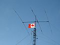
Yagi-Uda antennas are directional along the axis perpendicular to the dipole in the plane of the elements, from the reflector toward the driven element and the director(s). Typical spacings between elements vary from about 1/10 to 1/4 of a wavelength, depending on the specific design. The lengths of the directors are smaller than that of the driven element, which is smaller than that of the reflector(s) according to an elaborate design procedure. These elements are usually parallel in one plane, supported on a single crossbar known as a boom.The bandwidth of a Yagi-Uda antenna refers to the frequency range over which its directional gain and impedance match are preserved to within a stated criterion. The Yagi-Uda array in its basic form is very narrowband, with its performance already compromised at frequencies just a few percent above or below its design frequency. However using larger diameter conductors, among other techniques, the bandwidth can be substantially extended.
Yagi-Uda antennas used for amateur radio
Amateur radio
Amateur radio is the use of designated radio frequency spectrum for purposes of private recreation, non-commercial exchange of messages, wireless experimentation, self-training, and emergency communication...
are sometimes designed to operate on multiple bands. These elaborate designs create electrical breaks along each element (both sides) at which point a parallel LC
LC circuit
An LC circuit, also called a resonant circuit or tuned circuit, consists of an inductor, represented by the letter L, and a capacitor, represented by the letter C...
(inductor
Inductor
An inductor is a passive two-terminal electrical component used to store energy in a magnetic field. An inductor's ability to store magnetic energy is measured by its inductance, in units of henries...
and capacitor
Capacitor
A capacitor is a passive two-terminal electrical component used to store energy in an electric field. The forms of practical capacitors vary widely, but all contain at least two electrical conductors separated by a dielectric ; for example, one common construction consists of metal foils separated...
) circuit is inserted. This so-called trap has the effect of truncating the element at the higher frequency band, making it approximately a half wavelength in length. At the lower frequency, the entire element (including the remaining inductance due to the trap) is close to half-wave resonance, implementing a different Yagi-Uda antenna. Using a second set of traps a "triband" antenna can be resonant at three different bands. Given the associated costs of erecting an antenna and rotor system above a tower, the combination of antennas for three amateur bands in one unit is a very practical solution. The use of traps is not without disadvantages, however, as they reduce the bandwidth of the antenna on the individual bands and reduce the antenna's electrical efficiency.
Theory of Operation
Consider a Yagi-Uda consisting of a reflector, driven element and a single director as shown here. The driven element is typically a λ/2 dipole or folded dipole and is the only member of the structure that is directly excited (electrically connected to the feedline). All the other elements are considered parasitic. That is, they reradiate power which they receive from the driven element (they also interact with each other).One way of thinking about the operation of such an antenna is to consider a parasitic element to be a normal dipole element with a gap at its center, the feedpoint. Now instead of attaching the antenna to a load (such as a receiver) we connect it to a short circuit. As is well known in transmission line
Transmission line
In communications and electronic engineering, a transmission line is a specialized cable designed to carry alternating current of radio frequency, that is, currents with a frequency high enough that its wave nature must be taken into account...
theory, a short circuit reflects all of the incident power 180 degrees out of phase. So one could as well model the operation of the parasitic element as the superposition of a dipole element receiving power and sending it down a transmission line to a matched load, and a transmitter sending the same amount of power down the transmission line back toward the antenna element. If the wave from the transmitter were 180 degrees out of phase with the received wave at that point, it would be equivalent to just shorting out that dipole at the feedpoint (making it a solid element, as it is).
The fact that the parasitic element involved isn't exactly resonant but is somewhat shorter (or longer) than λ/2 modifies the phase of the element's current with respect to its excitation from the driven element. The so-called reflector element, being longer than λ/2, has an inductive reactance which means the phase of the its current lags the phase of the open-circuit voltage that would be induced by the received field. The director element, on the other hand, being shorter than λ/2 has a capacitive reactance with the voltage phase lagging that of the current. If the parasitic elements were broken in the center and driven with the same voltage applied to the center element, then such a phase difference in the currents would be implement an end-fire phased array
Phased array
In wave theory, a phased array is an array of antennas in which the relative phases of the respective signals feeding the antennas are varied in such a way that the effective radiation pattern of the array is reinforced in a desired direction and suppressed in undesired directions.An antenna array...
, enhancing the radiation in one direction and decreasing it in the opposite direction. Thus one can appreciate the mechanism by which parasitic elements of unequal length can lead to a unidirectional radiation pattern.
Analysis
While the above qualitative explanation is useful for understanding how parasitic elements can enhance the driven elements radiation in one direction at the expense of the other, the assumptions used are quite inaccurate. Since the so-called reflector, the longer parasitic element, has a current whose phase lags that of the driven element, one would expect the directivity to be in the direction of the reflector, opposite of the actual directional pattern of the Yagi-Uda antenna. In fact that would be the case were we to construct a phased array with rather closely spaced elements all driven by voltages in phase, as we posited.However these elements are not driven as such but receive their energy from the field created by the driven element, so we will find almost the opposite to be true. For now, consider that the parasitic element is also of length λ/2. Again looking at the parasitic element as a dipole which has been shorted at the feedpoint, we can see that if the parasitic element were to respond to the driven element with an open-circuit feedpoint voltage in phase with that applied to the driven element (which we'll assume for now) then the reflected wave from the short circuit would induce a current 180 degrees out of phase with the current in the driven element. This would tend to cancel the radiation of the driven element. However due to the reactance caused by the length difference, the phase lag of the current in the reflector, added to this 180 degree lag, results in a phase advance, and vice versa for the director. Thus the directivity of the array indeed is in the direction towards the director.
In the reverse direction, on the other hand, the additional delay of the wave from the director (black) due to the spacing between the two elements (about 35 degrees of phase delay) causes it to be about 180 degrees out of phase with the wave from the driven element (green). The net effect of these two waves, when added (bottom, left), is almost complete cancellation. The combination of the director's position and shorter length has thus obtained a unidirectional rather than the bidirectional response of the driven (half wave dipole) element alone.
A full analysis of such a system requires computing the mutual impedances between the dipole elements which implicitly takes into account the propagation delay due to the finite spacing between elements. We model element number j as having a feedpoint at the center with a voltage Vj and a current Ij flowing into it. Just considering two such elements we can write the voltage at each feedpoint in terms of the currents using the mutual impedances Zij:


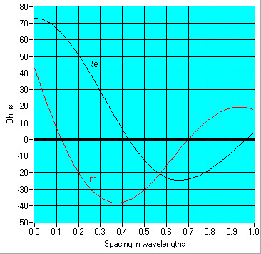
Z11 and Z22 are simply the ordinary driving point impedances of a dipole, thus 73+j43 ohms for a half wave element (or purely resistive for one slightly shorter, as is usually desired for the driven element). Due to the differences in the elements' lengths Z11 and Z22 have a substantially different reactive component. Due to reciprocity we know that Z21 Z12. Now the difficult computation is in determining that mutual impedance Z21 which requires a numerical solution. This has been computed for two exact half-wave dipole elements at various spacings in the accompanying graph.
The solution of the system then is as follows. Let the driven element be designated 1 so that V1 and I1 are the voltage and current supplied by the transmitter. The parasitic element is designated 2, and since it is shorted at its "feedpoint" we can write that V2 =0. Using the above relationships, then, we can solve for I2 in terms of I1:
-

- ∴

This is the current induced in the parasitic element due to the current I1 in the driven element. We can also solve for the voltage V1 at the feedpoint of the driven element using the earlier equation:

where we have substituted Z12 = Z21. The ratio of voltage to current at this point is the driving point impedance Zdp of the 2-element Yagi:
With only the driven element present the driving point impedance would have simply been Z11, but has now been modified by the presence of the parasitic element. And now knowing the phase (and amplitude) of I2 in relation to I1 as computed above allows us to determine the radiation pattern (gain as a function of direction) due to the currents flowing in these two elements. Solution of such an antenna with more than 2 elements proceeds along the same lines, setting each Vj=0 for all but the driven element, and solving for the currents in each element (and the voltage V1 at the feedpoint).
Design
There are no simple formulas for designing Yagi-Uda antennas due to the complex relationships between physical parameters such as element length, spacing, and diameter, and performance characteristics such as gain and input impedance. But using the above sort of analysis one can calculate the performance given a set of parameters and adjust them to optimize the gain (perhaps subject to some constraints). Since with an N element Yagi-Uda antenna, there are 2N-1 parameters to adjust (the element lengths and relative spacings), this is not a straight-forward problem at all. The mutual impedances plotted above only apply to λ/2 length elements, so these might need to be recomputed to get good accuracy. What's more, the current distribution along a real antenna element is only approximately given by the usual assumption of a classical standing wave, requiring a solution of Hallen's integral equation taking into account the other conductors. Such a complete exact analysis considering all of the interactions mentioned is rather overwhelming, and approximations are inevitably invoked, as we have done in the above example.Consequently, these antennas are often empirical designs using an element of trial and error
Trial and error
Trial and error, or trial by error, is a general method of problem solving, fixing things, or for obtaining knowledge."Learning doesn't happen from failure itself but rather from analyzing the failure, making a change, and then trying again."...
, often starting with an existing design modified according to one's hunch. The result might be checked by direct measurement or by computer simulation. A well-known reference employed in the latter approach is a report published by the National Bureau of Standards (NBS) (now the National Institute of Standards and Technology
National Institute of Standards and Technology
The National Institute of Standards and Technology , known between 1901 and 1988 as the National Bureau of Standards , is a measurement standards laboratory, otherwise known as a National Metrological Institute , which is a non-regulatory agency of the United States Department of Commerce...
(NIST)) that provides six basic designs derived from measurements conducted at 400 MHz and procedures for adapting these designs to other frequencies. These designs, and those derived from them, are sometimes referred to as "NBS yagis."
History
The Yagi-Uda antenna was invented in 1926 by Shintaro UdaShintaro Uda
Japanese inventor. Assistant of professor Hidetsugu Yagi at Tohoku University, where they invented the Yagi-Uda antenna in 1926. In February 1926, Yagi and Uda published their first report on the wave projector antenna in a Japanese publication. Yagi applied for patents on the new antenna both in...
of Tohoku Imperial University
Tohoku University
, abbreviated to , located in the city of Sendai, Miyagi Prefecture in the Tōhoku Region, Japan, is a Japanese national university. It is the third oldest Imperial University in Japan and is a member of the National Seven Universities...
, Sendai
Sendai, Miyagi
is the capital city of Miyagi Prefecture, Japan, and the largest city in the Tōhoku Region. In 2005, the city had a population of one million, and was one of Japan's 19 designated cities...
, Japan
Japan
Japan is an island nation in East Asia. Located in the Pacific Ocean, it lies to the east of the Sea of Japan, China, North Korea, South Korea and Russia, stretching from the Sea of Okhotsk in the north to the East China Sea and Taiwan in the south...
, with the collaboration of Hidetsugu Yagi
Hidetsugu Yagi
Hidetsugu Yagi was a Japanese electrical engineer. When working at Tohoku University, he wrote several important articles that introduced a new antenna design by his colleague Shintaro Uda to the English-speaking world.The Yagi antenna, patented in 1926, allows directional communication using...
, also of Tohoku Imperial University. Hidetsugu Yagi attempted wireless energy transfer
Wireless energy transfer
Wireless energy transfer or wireless power is the transmission of electrical energy from a power source to an electrical load without artificial interconnecting conductors. Wireless transmission is useful in cases where interconnecting wires are inconvenient, hazardous, or impossible...
in February 1926 with this antenna. Yagi and Uda published their first report on the wave projector directional antenna. Yagi demonstrated a proof of concept
Proof of concept
A proof of concept or a proof of principle is a realization of a certain method or idea to demonstrate its feasibility, or a demonstration in principle, whose purpose is to verify that some concept or theory that has the potential of being used...
, but the engineering problems proved to be more onerous than conventional systems.
Yagi published the first English-language reference on the antenna in a 1928 survey article on short wave research in Japan and it came to be associated with his name. However, Yagi always acknowledged Uda's principal contribution to the design, and the proper name for the antenna is, as above, the Yagi-Uda antenna (or array).
The Yagi was first widely used during World War II
World War II
World War II, or the Second World War , was a global conflict lasting from 1939 to 1945, involving most of the world's nations—including all of the great powers—eventually forming two opposing military alliances: the Allies and the Axis...
for airborne radar
Radar
Radar is an object-detection system which uses radio waves to determine the range, altitude, direction, or speed of objects. It can be used to detect aircraft, ships, spacecraft, guided missiles, motor vehicles, weather formations, and terrain. The radar dish or antenna transmits pulses of radio...
sets, because of its simplicity and directionality. Despite its being invented in Japan, many Japanese radar engineers were unaware of the design until very late in the war, partly due to rivalry between the Army and Navy. The Japanese military authorities first became aware of this technology after the Battle of Singapore
Battle of Singapore
The Battle of Singapore was fought in the South-East Asian theatre of the Second World War when the Empire of Japan invaded the Allied stronghold of Singapore. Singapore was the major British military base in Southeast Asia and nicknamed the "Gibraltar of the East"...
when they captured the notes of a British radar technician that mentioned "yagi antenna". Japanese intelligence officers did not even recognise that Yagi was a Japanese name in this context. When questioned, the technician said it was an antenna named after a Japanese professor. (This story is analogous to the story of American intelligence officers interrogating German rocket scientists and finding out that Robert Goddard was the real pioneer of rocket technology even though he was not well known in the US at that time.)
A horizontally polarized array can be seen under the left leading edge of Grumman F4F, F6F, TBF Avenger
TBF Avenger
The Grumman TBF Avenger was a torpedo bomber developed initially for the United States Navy and Marine Corps, and eventually used by several air or naval arms around the world....
carrier-based US Navy aircraft. Vertically polarized arrays can be seen on the cheeks of the P-61 and on the nose cone
Nose cone
The term nose cone is used to refer to the forwardmost section of a rocket, guided missile or aircraft. The cone is shaped to offer minimum aerodynamic resistance...
s of many WWII aircraft, notably the Lichtenstein radar
Lichtenstein radar
Lichtenstein radar was a German airborne radar in use during World War II. It was available in at least four major revisions, the FuG 202 Lichtenstein B/C, FuG 212 Lichtenstein C-1, FuG 220 Lichtenstein SN-2 and FuG 228 Lichtenstein SN-3.- FuG 202 Lichtenstein B/C :Early FuG 202 Lichtenstein B/C...
-equipped examples of the German Junkers Ju 88
Junkers Ju 88
The Junkers Ju 88 was a World War II German Luftwaffe twin-engine, multi-role aircraft. Designed by Hugo Junkers' company through the services of two American aviation engineers in the mid-1930s, it suffered from a number of technical problems during the later stages of its development and early...
R-1 fighter-bomber
Fighter-bomber
A fighter-bomber is a fixed-wing aircraft with an intended primary role of light tactical bombing and also incorporating certain performance characteristics of a fighter aircraft. This term, although still used, has less significance since the introduction of rockets and guided missiles into aerial...
, and the British Bristol Beaufighter
Bristol Beaufighter
The Bristol Type 156 Beaufighter, often referred to as simply the Beau, was a British long-range heavy fighter modification of the Bristol Aeroplane Company's earlier Beaufort torpedo bomber design...
night-fighter and Short Sunderland
Short Sunderland
The Short S.25 Sunderland was a British flying boat patrol bomber developed for the Royal Air Force by Short Brothers. It took its service name from the town and port of Sunderland in northeast England....
flying-boat. Indeed, the latter had so many antenna elements arranged on its back it was nicknamed the "Flying Porcupine" by German airmen.
Yagi-Uda antennas are routinely made with rather high gains (over 10dB) making them a common choice for directional antennas especially in VHF and UHF communications systems where a narrowband antenna is acceptable. Only at higher UHF and microwave frequencies are parabolic reflectors and other so-called aperture antennas of a practical size; these can easily achieve yet higher gains.
The Yagi-Uda antenna was named an IEEE Milestone in 1995.
See also
- Antenna (radio)Antenna (radio)An antenna is an electrical device which converts electric currents into radio waves, and vice versa. It is usually used with a radio transmitter or radio receiver...
- Larmor formulaLarmor formulaIn physics, in the area of electrodynamics, the Larmor formula is used to calculate the total power radiated by a nonrelativistic point charge as it accelerates. It was first derived by J. J...
- Radio direction finderRadio direction finderA radio direction finder is a device for finding the direction to a radio source. Due to low frequency propagation characteristic to travel very long distances and "over the horizon", it makes a particularly good navigation system for ships, small boats, and aircraft that might be some distance...
- Radio direction finding
External links
- D. Jefferies, "Yagi-Uda antennas". 2004.
- Yagi-Uda Antenna. Simple information on basic design, project and measure of Yagi-Uda antenna. 2008
- Yagi-Uda Antennas www.antenna-theory.com