
Universal joint
Encyclopedia
Gerolamo Cardano
Gerolamo Cardano was an Italian Renaissance mathematician, physician, astrologer and gambler...
joint, Hardy-Spicer
Clarence W. Spicer
Clarence W. Spicer is known for inventing the Spicer joint, a type of universal joint.Dr. Spicer attended Alfred University from 1891 to 1894. He received the patent for his joint in 1903 while studying at Cornell University, and began manufacturing his invention as Spicer Manufacturing Company in...
joint, or Hooke
Robert Hooke
Robert Hooke FRS was an English natural philosopher, architect and polymath.His adult life comprised three distinct periods: as a scientific inquirer lacking money; achieving great wealth and standing through his reputation for hard work and scrupulous honesty following the great fire of 1666, but...
's joint is a joint or coupling
Coupling
A coupling is a device used to connect two shafts together at their ends for the purpose of transmitting power. Couplings do not normally allow disconnection of shafts during operation, however there are torque limiting couplings which can slip or disconnect when some torque limit is exceeded.The...
in a rigid rod that allows the rod to 'bend' in any direction, and is commonly used in shafts that transmit rotary motion. It consists of a pair of hinge
Hinge
A hinge is a type of bearing that connects two solid objects, typically allowing only a limited angle of rotation between them. Two objects connected by an ideal hinge rotate relative to each other about a fixed axis of rotation. Hinges may be made of flexible material or of moving components...
s located close together, oriented at 90° to each other, connected by a cross shaft.
History
The main concept of the universal joint is based on the design of gimbalGimbal
A gimbal is a pivoted support that allows the rotation of an object about a single axis. A set of two gimbals, one mounted on the other with pivot axes orthogonal, may be used to allow an object mounted on the innermost gimbal to remain immobile regardless of the motion of its support...
s, which have been in use since antiquity. One anticipation of the universal joint was its use by the Ancient Greeks on ballistae. The first person known to have suggested its use for transmitting motive power was Gerolamo Cardano
Gerolamo Cardano
Gerolamo Cardano was an Italian Renaissance mathematician, physician, astrologer and gambler...
, an Italian mathematician, in 1545, although it is unclear whether he produced a working model. In Europe, the device is often called the Cardan joint or Cardan shaft. Christopher Polhem
Christopher Polhem
Christopher Polhammar , better known as , which he took after his ennoblement, was a Swedish scientist, inventor and industrialist. He made significant contributions to the economic and industrial development of Sweden, particularly mining.-Biography:Polhem was born on the island of Gotland...
of Sweden later reinvented it, giving rise to the name Polhemsknut in Swedish.
The mechanism was later described in Technica curiosa sive mirabilia artis (1664) by Gaspar Schott
Gaspar Schott
Gaspar Schott was a German Jesuit and scientist, specializing in the fields of physics, mathematics and natural philosophy, and known for his piety.-Biography:...
, who called it the paradoxum, but mistakenly claimed that it was a constant-velocity joint.
Shortly afterwards, between 1667 and 1675, Robert Hooke
Robert Hooke
Robert Hooke FRS was an English natural philosopher, architect and polymath.His adult life comprised three distinct periods: as a scientific inquirer lacking money; achieving great wealth and standing through his reputation for hard work and scrupulous honesty following the great fire of 1666, but...
analysed the joint and found that its speed of rotation was nonuniform, but that this property could be used to track the motion of the shadow on the face of a sundial. In fact, the component of the equation of time
Equation of time
The equation of time is the difference between apparent solar time and mean solar time. At any given instant, this difference will be the same for every observer...
which accounts for the tilt of the equatorial plane relative to the ecliptic is entirely analogous to the mathematical description of the universal joint. The first recorded use of the term universal joint for this device was by Hooke in 1676, in his book Helioscopes. He published a description in 1678, resulting in the use of the term Hooke's joint in the English-speaking world. In 1683, Hooke proposed a solution to the nonuniform rotary speed of the universal joint: a pair of Hooke's joints 90° out of phase at either end of an intermediate shaft, an arrangement that is now known as a type of constant-velocity joint
Constant-velocity joint
Constant-velocity joints allow a drive shaft to transmit power through a variable angle, at constant rotational speed, without an appreciable increase in friction or play. They are mainly used in front wheel drive and all wheel drive cars...
.
The term universal joint was used in the 18th century and was in common use in the 19th century. Edmund Morewood's 1844 patent for a metal coating machine called for a universal joint, by that name, to accommodate small alignment errors between the engine and rolling mill shafts. Lardner's 1877 Handbook described both simple and double universal joints, and noted that they were much used in the line shaft
Line shaft
A line shaft is a power transmission system used extensively during the Industrial Revolution. Prior to the widespread use of electric motors small enough to be connected directly to each piece of machinery, line shafting was used to distribute power from a large central power source to machinery...
systems of cotton mills. Jules Weisbach described the mathematics of the universal joint and double universal joint in his treatise on mechanics published in English in 1883.
19th century uses of universal joints spanned a wide range of applications. Numerous universal joints were used to link the control shafts of the Northumberland telescope at Cambridge University in 1843. Ephriam Shay's locomotive
Shay locomotive
The Shay locomotive was the most widely used geared steam locomotive. The locomotives were built to the patents of Ephraim Shay, who has been credited with the popularization of the concept of a geared steam locomotive...
patent of 1881, for example, used double universal joints in the locomotive's drive shaft. Charles Amidon used a much smaller universal joint in his bit-brace
Brace (tool)
A brace or brace and bit is a hand tool used to drill holes, usually in wood. Pressure is applied to the top and the tool is rotated with a U-shaped grip....
patented 1884.
The term Cardan joint appears to be a latecomer to the English language. Many early uses in the 19th century appear in translations from French
French language
French is a Romance language spoken as a first language in France, the Romandy region in Switzerland, Wallonia and Brussels in Belgium, Monaco, the regions of Quebec and Acadia in Canada, and by various communities elsewhere. Second-language speakers of French are distributed throughout many parts...
or are strongly influenced by French usage. Examples include an 1868 report on the Exposition Universelle of 1867
Exposition Universelle (1867)
The Exposition Universelle of 1867 was a World Exposition held in Paris, France, in 1867.-Conception:In 1864, Emperor Napoleon III decreed that an international exposition should be held in Paris in 1867. A commission was appointed with Prince Jerome Napoleon as president, under whose direction...
and an article on the dynamometer
Dynamometer
A dynamometer or "dyno" for short, is a device for measuring force, moment of force , or power. For example, the power produced by an engine, motor or other rotating prime mover can be calculated by simultaneously measuring torque and rotational speed .A dynamometer can also be used to determine...
translated from French in 1881.
Equation of motion
-
 The angle of rotation for axle 1
 -
 The angle of rotation for axle 2
 -
 The bend angle of the joint, or angle of the axles with respect to each other, with zero being parallel or straight through.
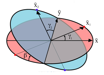
These variables are illustrated in the diagram on the right. Also shown are a set of fixed coordinate axes with unit vectors
 and
and  and the planes of rotation
Plane of rotation
In geometry, a plane of rotation is an abstract object used to describe or visualise rotations in space. In three dimensions it is an alternative to the axis of rotation, but unlike the axis of rotation it can be used in other dimensions, such as two, four or more dimensions.Mathematically such...
of each axle. These planes of rotation are perpendicular to the axes of rotation and do not move as the axles rotate. The two axles are joined by a gimbal which is not shown. However, axle 1 attaches to the gimbal at the red points on the red plane of rotation in the diagram, and axle 2 attaches at the blue points on the blue plane. Coordinate systems fixed with respect to the rotating axles are defined as having their x-axis unit vectors (
 and
and  ) pointing from the origin towards one of the connection points. As shown in the diagram,
  is at angle
  with respect to its beginning position along the x axis and
  is at angle
  with respect to its beginning position along the y axis.
 is confined to the "red plane" in the diagram and is related to
  by:
by:
 is confined to the "blue plane" in the diagram and is the result of the unit vector on the x axis
  being rotated through Euler angles
Euler angles
The Euler angles are three angles introduced by Leonhard Euler to describe the orientation of a rigid body. To describe such an orientation in 3-dimensional Euclidean space three parameters are required...
 ]:
]:
A constraint on the
 and
and  vectors is that since they are fixed in the gimbal, they must remain at right angles to each other:
Thus the equation of motion relating the two angular positions is given by:

with a formal solution for
 :
:
The solution for
 is not unique since the arctangent function is multivalued, however it is required that the solution for
  be continuous over the angles of interest. For example, the following explicit solution using the atan2
Atan2
In trigonometry, the two-argument function atan2 is a variation of the arctangent function. For any real arguments and not both equal to zero, is the angle in radians between the positive -axis of a plane and the point given by the coordinates on it...
(y,x) function will be valid for
 :
:
The angles
 and
and  in a rotating joint will be functions of time. Differentiating the equation of motion with respect to time and using the equation of motion itself to eliminate a variable yields the relationship between the angular velocities
  and
and  :
: |
 |
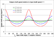
Angular (rotational) output shaft speed  versus rotation angle versus rotation angle  for different bend angles for different bend angles  of the joint of the joint |
Output shaft rotation angle,  , versus input shaft rotation angle, , versus input shaft rotation angle,  , for different bend angles, , for different bend angles,  , of the joint , of the joint |

As shown in the plots, the angular velocities are not linearly related, but rather are periodic with a period twice that of the rotating shafts. The angular velocity equation can again be differentiated to get the relation between the angular accelerations
 and
and  :
:
Double Cardan Shaft
Even when the driving and driven shafts are at equal angles with respect to the intermediate shaft, if these angles are greater than zero, oscillating moments are applied to the three shafts as they rotate. These tend to bend them in a direction perpendicular to the common plane of the shafts. This applies forces to the support bearings and can cause "launch shudder" in rear wheel drive vehicles. The intermediate shaft will also have a sinusoidal
Sine wave
The sine wave or sinusoid is a mathematical function that describes a smooth repetitive oscillation. It occurs often in pure mathematics, as well as physics, signal processing, electrical engineering and many other fields...
component to its angular velocity, which contributes to vibration and stresses.
Mathematically, this can be shown as follows: If
 and
and  are the angles for the input and output of the universal joint connecting the drive and the intermediate shafts respectively, and
  and
and  are the angles for the input and output of the universal joint connecting the intermediate and the output shafts respectively, and each pair are at angle
  with respect to each other, then:
If the second universal joint is rotated 90 degrees with respect to the first, then
 . Using the fact that
  yields:
and it is seen that the output drive is just 90 degrees out of phase with the input shaft, yielding a constant-velocity drive.
Double Cardan Joint
A double cardan joint consists of two universal joints mounted back to back, with no intermediate shaft. The second UJ cancels the velocity errors introduced by the single joint, and so they act as a CV joint.Thompson Coupling
A Thompson Coupling is a refined version of the double Cardan joint. It offers slightly increased efficiency with the penalty of some increase in complexity.See also
- Cardan shaft
- Constant-velocity jointConstant-velocity jointConstant-velocity joints allow a drive shaft to transmit power through a variable angle, at constant rotational speed, without an appreciable increase in friction or play. They are mainly used in front wheel drive and all wheel drive cars...
- Elastic couplingElastic couplingDr. Ing. Leonhard Geislinger invented the torsionally Elastic coupling in 1958. It is also called flexible coupling. It was originally a side product of the development for thermo-pneumatic locomotives, but unlike the trains, it was a big success....
- Gear coupling
- Rag jointRag jointA rag joint refers to certain flexible joints found on automobiles. They are typically found on steering shafts that connect the steering wheel to the steering gear input shaft, usually at the steering gear end. They provide a small amount of flex for a steering shaft within a few degrees of the...
- Canfield jointCanfield jointThe Canfield joint is a mechanism that allows for full hemispherical motion from whatever connects to it. Invented by Dr. Stephen Canfield of the Tennessee Tech University, this joint was developed specifically for spacecraft thrusters and solar panels...
External links
- http://demonstrations.wolfram.com/UniversalJoint/ by Sándor Kabai, Wolfram Demonstrations ProjectWolfram Demonstrations ProjectThe Wolfram Demonstrations Project is hosted by Wolfram Research, whose stated goal is to bring computational exploration to the widest possible audience. It consists of an organized, open-source collection of small interactive programs called Demonstrations, which are meant to visually and...
. - DIY: Replacing Universal Joints, About.com.
- Thompson Couplings Limited - Explanation of the Thompson coupling
- The Thompson Coupling - invented by Glenn Thompson ABC Television - The New Inventors - broadcast Feb 2007 - Constant velocity coupling
- About universal joints at McMaster Carr