

Universal Serial Bus
Encyclopedia
USB is an industry standard
developed in the mid-1990s that defines the cables, connectors and protocol
s used in a bus for connection, communication and power supply between computer
s and electronic devices.
USB was designed to standardize the connection of computer peripherals, such as keyboards, pointing devices
, digital cameras, printers, portable media player
s, disk drives and network adapters to personal computer
s, both to communicate and to supply electric power
. It has become commonplace on other devices, such as smartphone
s, PDA
s and video game console
s. USB has effectively replaced a variety of earlier interfaces, such as serial
and parallel port
s, as well as separate power chargers for portable devices.
Up to 2008, about 2 billion USB devices were sold each year, and approximately 6 billion devices were sold in total.
 A group of seven companies began development on USB in 1994: Compaq
, DEC
, IBM
, Intel, Microsoft
, NEC
and Nortel
. The goal was to make it fundamentally easier to connect external devices to PCs by replacing the multitude of connectors at the back of PCs, addressing the usability issues of existing interfaces, and simplifying software configuration of all devices connected to USB, as well as permitting greater data rates for external devices. The first silicon for USB was made by Intel in 1995.
The original USB 1.0 specification, which was introduced in January 1996, defined data transfer rates of 1.5 Mbit/s "Low Speed" and 12 Mbit/s "Full Speed". The first widely used version of USB was 1.1, which was released in September 1998. The 12 Mbit/s data rate was intended for higher-speed devices such as disk drives, and the lower 1.5 Mbit/s rate for low data rate devices such as joystick
s.
The USB 2.0 specification was released in April 2000 and was ratified by the USB Implementers Forum
(USB-IF) at the end of 2001. Hewlett-Packard
, Intel, Lucent Technologies
(now Alcatel-Lucent), NEC and Philips
jointly led the initiative to develop a higher data transfer rate, with the resulting specification achieving 480 Mbit/s, a fortyfold increase over the original USB 1.1 specification.
The USB 3.0 specification was published on 12 November 2008. Its main goals were to increase the data transfer rate (up to 5 Gbit/s), to decrease power consumption, to increase power output, and to be backwards-compatible with USB 2.0. USB 3.0 includes a new, higher speed bus called SuperSpeed in parallel with the USB 2.0 bus. For this reason, the new version is also called SuperSpeed. The first USB 3.0 equipped devices were presented in January 2010.

), and the specification considers it reasonable to achieve around 3.2 Gbit/s (0.4 GB/s or 400 MB/s), increasing as hardware advances in the future take hold.
design, consisting of a host
, a multitude of downstream USB ports, and multiple peripheral devices connected in a tiered-star topology. Additional USB hub
s may be included in the tiers, allowing branching into a tree structure with up to five tier levels. A USB host may have multiple host controllers and each host controller may provide one or more USB ports. Up to 127 devices, including hub devices if present, may be connected to a single host controller.
USB devices are linked in series through hubs. There always exists one hub known as the root hub, which is built into the host controller.
A physical USB device may consist of several logical sub-devices that are referred to as device functions. A single device may provide several functions, for example, a webcam
(video device function) with a built-in microphone (audio device function). Such a device is called a compound device in which each logical device is assigned a distinctive address by the host and all logical devices are connected to a built-in hub to which the physical USB wire is connected. A host assigns one and only one device address to a function.
.svg.png) USB device communication is based on pipes (logical channels). A pipe is a connection from the host controller to a logical entity, found on a device, and named an endpoint
USB device communication is based on pipes (logical channels). A pipe is a connection from the host controller to a logical entity, found on a device, and named an endpoint
. Because pipes correspond 1-to-1 to endpoints, the terms are sometimes used interchangeably. A USB device can have up to 32 endpoints: 16 into the host controller and 16 out of the host controller. The USB standard reserves one endpoint of each type, leaving a theoretical maximum of 30 for normal use. USB devices seldom have this many endpoints.
There are two types of pipes: stream and message pipes depending on the type of data transfer.
A stream pipe is a uni-directional pipe connected to a uni-directional endpoint that transfers data using an isochronous, interrupt, or bulk transfer. A message pipe is a bi-directional pipe connected to a bi-directional endpoint that is exclusively used for control data flow. An endpoint is built into the USB device by the manufacturer and therefore exists permanently. An endpoint of a pipe is addressable with a tuple
(device_address, endpoint_number) as specified in a TOKEN packet that the host sends when it wants to start a data transfer session. If the direction of the data transfer is from the host to the endpoint, an OUT packet (a specialization of a TOKEN packet) having the desired device address and endpoint number is sent by the host. If the direction of the data transfer is from the device to the host, the host sends an IN packet instead. If the destination endpoint is a uni-directional endpoint whose manufacturer's designated direction does not match the TOKEN packet (e.g., the manufacturer's designated direction is IN while the TOKEN packet is an OUT packet), the TOKEN packet will be ignored. Otherwise, it will be accepted and the data transaction can start. A bi-directional endpoint, on the other hand, accepts both IN and OUT packets.
 Endpoints are grouped into interfaces and each interface is associated with a single device function. An exception to this is endpoint zero, which is used for device configuration and which is not associated with any interface. A single device function composed of independently controlled interfaces is called a composite device. A composite device only has a single device address because the host only assigns a device address to a function.
When a USB device is first connected to a USB host, the USB device enumeration process is started. The enumeration starts by sending a reset signal to the USB device. The data rate of the USB device is determined during the reset signaling. After reset, the USB device's information is read by the host and the device is assigned a unique 7-bit address. If the device is supported by the host, the device driver
s needed for communicating with the device are loaded and the device is set to a configured state. If the USB host is restarted, the enumeration process is repeated for all connected devices.
The host controller directs traffic flow to devices, so no USB device can transfer any data on the bus without an explicit request from the host controller. In USB 2.0, the host controller polls
the bus for traffic, usually in a round-robin
fashion. The slowest device connected to a controller sets the bandwidth of the interface. For SuperSpeed USB (defined since USB 3.0), connected devices can request service from host. Because there are two separate controllers in each USB 3.0 host, USB 3.0 devices will transmit and receive at USB 3.0 data rates regardless of USB 2.0 or earlier devices connected to that host. Operating data rates for them will be set in the legacy manner.
Device classes include:
. This generality is because many systems can be controlled with the familiar metaphor of file manipulation within directories (the process of making a novel device look like a familiar device is also known as extension). The ability to boot a write-locked SD card with a USB adapter is particularly advantageous for maintaining the integrity and non-corruptible, pristine state of the booting medium.
Though most newer computers are capable of booting off USB mass storage devices, USB is not intended to be a primary bus for a computer's internal storage: buses such as Parallel ATA (PATA or IDE), Serial ATA
(SATA), or SCSI
fulfill that role in PC class computers. However, USB has one important advantage in that it is possible to install and remove devices without rebooting the computer (hot-swapping), making it useful for mobile peripherals, including drives of various kinds. Originally conceived and still used today for optical storage devices (CD-RW
drives, DVD
drives and so on), several manufacturers offer external portable USB hard disk drives, or empty enclosures for disk drives, which offer performance comparable to internal drives, limited by the current number and type of attached USB devices and by the upper limit of the USB interface (in practice about 30 MB/s for USB 2.0 and potentially 400 MB/s or more for USB 3.0). These external drives have typically included a "translating device" that bridges between a drive's interface to a USB interface port. Functionally, the drive appears to the user much like an internal drive. Other competing standards for external drive connectivity include eSATA, ExpressCard
(now at version 2.0), and FireWire (IEEE 1394).
Another use for USB mass storage devices is the portable execution of software applications (such as web browsers and VoIP clients) with no need to install them on the host computer.
connectors to USB.
USB mice and keyboards can usually be used with older computers that have PS/2 connector
s with the aid of a small USB-to-PS/2 adapter. Such adaptors contain no logic circuitry
: the hardware in the USB keyboard or mouse is designed to detect whether it is connected to a USB or PS/2 port, and communicate using the appropriate protocol. Converters also exist to allow PS/2 keyboards and mice (usually one of each) to be connected to a USB port. These devices present two HID endpoints to the system and use a microcontroller
to perform bidirectional translation of data between the two standards.
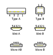
 The connectors specified by the USB committee were designed to support a number of USB's underlying goals, and to reflect lessons learned from the menagerie of connectors which have been used in the computer industry. The connector mounted on the host or device is called the receptacle, and the connector attached to the cable is called the plug. In the case of an extension cable, the connector on one end is a receptacle. The official USB specification documents periodically define the term male to represent the plug, and female to represent the receptacle.
 By design, it is difficult to attach a USB connector incorrectly. Connectors cannot be plugged in upside down and it is clear from the physical act of making a connection, when the plug and receptacle are correctly mated. The USB specification states that the required USB Icon is to be "embossed" on the "topside" of the USB plug, which "provides easy user recognition and facilitates alignment during the mating process". The specification also shows that the "recommended" (optional) "Manufacturer's logo" ("engraved" on the diagram but not specified in the text) is on the opposite side of the USB Icon. The specification further states "the USB Icon is also located adjacent to each receptacle. Receptacles should be oriented to allow the icon on the plug to be visible during the mating process". However, the specification does not consider the height of the device compared to the eye level height of the user, so the side of the cable that is "visible" when mated to a computer on a desk can depend on whether the user is standing or kneeling.
Only moderate insertion/removal force is needed. USB cables and small USB devices are held in place by the gripping force from the receptacle (without need of the screws, clips, or thumb-turns other connectors have required). The force needed to make or break a connection is modest, allowing connections to be made in awkward circumstances (i.e., behind a floor-mounted chassis, or from below) or by those with motor disabilities.
The standard connectors were deliberately intended to enforce the directed topology
of a USB network: type A connectors on host devices that supply power and type B connectors on target devices that receive power. This prevents users from accidentally connecting two USB power supplies to each other, which could lead to dangerously high currents, circuit failures, or even fire. USB does not support cyclical networks and the standard connectors from incompatible USB devices are themselves incompatible. Unlike other communications systems (e.g. network cabling) gender changer
s make little sense with USB and are almost never used.
The connector construction always ensures that the external sheath on the plug makes contact with its counterpart in the receptacle before any of the four connectors within make electrical contact. The external metallic sheath is typically connected to system ground, thus dissipating damaging static charges. This enclosure design also provides a degree of protection from electromagnetic interference to the USB signal while it travels through the mated connector pair (the only location when the otherwise twisted data pair travels in parallel). In addition, because of the required sizes of the power and common connections, they are made after the system ground but before the data connections. This type of staged make-break timing allows for electrically safe hot-swapping.
The newer Micro-USB receptacles are designed for up to 10,000 cycles of insertion and removal between the receptacle and plug, compared to 1,500 for the standard USB and 5,000 for the Mini-USB receptacle. This is accomplished by adding a locking device and by moving the leaf-spring connector from the jack to the plug, so that the most-stressed part is on the cable side of the connection. This change was made so that the connector on the less expensive cable would bear the most wear instead of the more expensive micro-USB device.
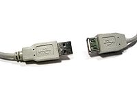
In general, cables have only plugs (very few have a receptacle on one end, although extension cables with a standard A plug and jack are sold), and hosts and devices have only receptacles. Hosts almost universally have type-A receptacles, and devices one or another type-B variety. Type-A plugs mate only with type-A receptacles, and type-B with type-B; they are deliberately physically incompatible. However, an extension to USB standard specification called USB On-The-Go
allows a single port to act as either a host or a device—chosen by which end of the cable plugs into the receptacle on the unit. Even after the cable is hooked up and the units are communicating, the two units may "swap" ends under program control. This capability is meant for units such as PDAs
in which the USB link might connect to a PC's host port as a device in one instance, yet connect as a host itself to a keyboard and mouse device in another instance.
USB 3.0 receptacles are electrically compatible with USB Standard 2.0 device plugs if they physically match. USB 3.0 type-A plugs and receptacles are completely backward compatible, and USB 3.0 type-B receptacles will accept USB 2.0 and earlier plugs. However, USB 3.0 type-B plugs will not fit into USB 2.0 and earlier receptacles. eSATAp
(eSATA/USB) port is also compatible with USB 2.0 devices.
The data connectors in the Standard-A plug are actually recessed in the plug as compared to the outside power connectors. This permits the power to connect first which prevents data errors by allowing the device to power up first and then transfer the data. Some devices will operate in different modes depending on whether the data connection is made. This difference in connection can be exploited by inserting the connector only partially. For example, some battery-powered MP3 players switch into file transfer mode and cannot play MP3 files while a USB plug is fully inserted, but can be operated in MP3 playback mode using USB power by inserting the plug only part way so that the power slots make contact while the data slots do not. This enables those devices to be operated in MP3 playback mode while getting power from the cable.
To reliably enable a charge-only feature, modern USB accessory peripherals now include charging cables that provide power connections to the host port but no data connections, and both home and vehicle charging docks are available that supply power from a converter device and do not include a host device and data pins, allowing any capable USB device to be charged and/or operated from a standard USB cable.
 The USB 2.0 Standard-A type of USB plug is a flattened rectangle which inserts into a "downstream-port" receptacle on the USB host, or a hub, and carries both power and data. This plug is frequently seen on cables that are permanently attached to a device, such as one connecting a keyboard or mouse to the computer via usb connection.
USB connections eventually wear out as the connection loosens through repeated plugging and unplugging. The lifetime of a USB-A male connector is approximately 1,500 connect/disconnect cycles.
A Standard-B plug—which has a square shape with bevelled exterior corners—typically plugs into an "upstream receptacle" on a device that uses a removable cable, e.g. a printer. A Type B plug delivers power in addition to carrying data. On some devices, the Type B receptacle has no data connections, being used solely for accepting power from the upstream device. This two-connector-type scheme (A/B) prevents a user from accidentally creating an electrical loop.
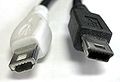 Various connectors have been used for smaller devices such as PDAs, mobile phones or digital cameras. These include the now-deprecated (but standardized) Mini-A and the currently standard Mini-B, Micro-A, and Micro-B connectors.
The Mini-A and Mini-B plugs are approximately 3 by 7 mm. The micro-USB plugs have a similar width and approximately half the thickness, enabling their integration into thinner portable devices. The mini-A connector is 6.85 by 1.8 mm with a maximum overmold size of 11.7 by 8.5 mm. The mini-B connector is 6.85 by 1.8 mm with a maximum overmold size of 10.6 by 8.5 mm.
The Micro-USB connector was announced by the USB-IF
on 4 January 2007. The Mini-A connector and the Mini-AB receptacle connector were deprecated on 23 May 2007. , many currently available devices and cables still use Mini plugs, but the newer Micro connectors are being widely adopted and as of December 2010, the Micro connectors are the most widely used. The thinner micro connectors are intended to replace the Mini plugs in new devices including smartphone
s and personal digital assistant
s. The Micro plug design is rated for at least 10,000 connect-disconnect cycles which is significantly more than the Mini plug design. The Universal Serial Bus Micro-USB Cables and Connectors Specification details the mechanical characteristics of Micro-A plug
s, Micro-AB receptacles, and Micro-B plugs and receptacles, along with a Standard-A receptacle to Micro-A plug adapter.
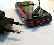
The cellular phone carrier group, Open Mobile Terminal Platform
(OMTP) in 2007 have endorsed Micro-USB as the standard connector for data and power on mobile devices. These include various types of battery chargers, allowing Micro-USB to be the single external cable link needed by some devices.
As of 30 January 2009 Micro-USB has been accepted and is being used by almost all cell phone manufacturers as the standard charging port (including HTC, Motorola, Nokia, LG, Hewlett-Packard, Samsung, Sony Ericsson, Research In Motion) in most of the world.
On 29 June 2009, following a request from the European Commission
and in close co-operation with the Commission services, major producers of mobile phones have agreed in a Memorandum of Understanding
("MoU") to harmonise chargers for data-enabled mobile phones sold in the European Union. Industry commits to provide charger compatibility on the basis of the Micro-USB connector. Consumers will be able to purchase mobile phones without a charger, thus logically reducing their cost. Following a mandate from the European Commission, the European Standardisation Bodies CEN-CENELEC and ETSI have now made available the harmonised standards needed for the manufacture of data-enabled mobile phones compatible with the new common External Power Supply
(EPS) based on micro-USB.
In addition, on 22 October 2009 the International Telecommunication Union
(ITU) has also announced that it had embraced micro-USB as the Universal Charger Solution its "energy-efficient one-charger-fits-all new mobile phone solution", and added: "Based on the Micro-USB interface, UCS chargers will also include a 4-star or higher efficiency rating—up to three times more energy-efficient than an unrated charger".
A USB On-The-Go
device is required to have one, and only one USB connector: a Mini-AB or Micro-AB receptacle. This receptacle is capable of accepting both Mini-A and Mini-B plugs, and alternatively, Micro-A and Micro-B plugs, attached to any of the legal cables and adapters as defined in Micro-USB1.01.
The OTG device with the A-plug inserted is called the A-device and is responsible for powering the USB interface when required and by default assumes the role of host. The OTG device with the B-plug inserted is called the B-device and by default assumes the role of peripheral. An OTG device with no plug inserted defaults to acting as a B-device. If an application on the B-device requires the role of host, then the HNP protocol is used to temporarily transfer the host role to the B-device.
OTG devices attached either to a peripheral-only B-device or a standard/embedded host will have their role fixed by the cable since in these scenarios it is only possible to attach the cable one way around.
NS: non-standard, existing for specific proprietary purposes, and not interoperable with USB-IF compliant equipment.
In addition to the above cable assemblies comprising two plugs, an "adapter" cable with a Micro-A plug and a Standard-A receptacle is compliant with USB specifications. Other combinations of connectors are not compliant. However, some older devices and cables with Mini-A connectors have been certified by USB-IF. The Mini-A connector has been deprecated: there will be no new certification of assemblies using Mini-A connector.


 The data cables for USB 1.x and USB 2.x use a twisted pair
to reduce noise and crosstalk
. USB 3.0 cables contain twice as many wires as USB 2.x to support SuperSpeed data transmission, and are thus larger in diameter.
The USB 1.1 Standard specifies that a standard cable can have a maximum length of 3 meters with devices operating at Low Speed (1.5 Mb/s), and a maximum length of 5 meters with devices operating at Full Speed (12 Mb/s).
USB 2.0 provides for a maximum cable length of 5 meters for devices running at Hi Speed (480 Mb/s). The primary reason for this limit is the maximum allowed round-trip delay of about 1.5 μs. If USB host commands are unanswered by the USB device within the allowed time, the host considers the command lost. When adding USB device response time, delays from the maximum number of hubs added to the delays from connecting cables, the maximum acceptable delay per cable amounts to 26 ns. The USB 2.0 specification requires cable delay to be less than 5.2 ns per meter (192,000 km/s, which is close to the maximum achievable transmission speed for standard copper wire).
The USB 3.0 standard does not directly specify a maximum cable length, requiring only that all cables meet an electrical specification: for copper cabling with AWG
26 wires the maximum practical length is 3 metres (9.8 ft).
A unit load is defined as 100 mA in USB 2.0, and 150 mA in USB 3.0. A device may draw a maximum of 5 unit loads (500 mA) from a port in USB 2.0; 6 (900 mA) in USB 3.0. There are two types of devices: low-power and high-power. A low-power device draws at most 1 unit load, with minimum operating voltage of 4.4 V in USB 2.0, and 4 V in USB 3.0. A high-power device draws the maximum number of unit loads permitted by the standard. Every device functions initially as low-power but the device may request high-power and will get it if the power is available on the providing bus.
Some devices, such as high-speed external disk drives, require more than 500 mA of current and therefore cannot be powered from one USB 2.0 port. Such devices usually come with Y-shaped cable that has two USB connectors to be plugged into a computer. With such a cable, a device can draw power from two USB ports simultaneously.
A bus-powered hub initializes itself at 1 unit load and transitions to maximum unit loads after it completes hub configuration. Any device connected to the hub will draw 1 unit load regardless of the current draw of devices connected to other ports of the hub (i.e. one device connected on a four-port hub will draw only 1 unit load despite the fact that more unit loads are being supplied to the hub).
A self-powered hub will supply maximum supported unit loads to any device connected to it. In addition, the VBUS will present 1 unit load upstream for communication if parts of the Hub are powered down.
In Battery Charging Specification, new powering modes are added to the USB specification. A host or hub Charging Downstream Port can supply a maximum of 1.5 A when communicating at low-bandwidth or full-bandwidth, a maximum of 900 mA when communicating at high-bandwidth, and as much current as the connector will safely handle when no communication is taking place; USB 2.0 standard-A connectors are rated at 1.5 A by default. A Dedicated Charging Port can supply a maximum of 1.8 A of current at 5.25 V. A portable device can draw up to 1.8 A from a Dedicated Charging Port. The Dedicated Charging Port shorts the D+ and D- pins with a resistance of at most 200 Ω. The short disables data transfer, but allows devices to detect the Dedicated Charging Port and allows very simple, high current chargers to be manufactured. The increased current (faster, 9 W charging) happens if both the host/hub and devices implement the new charging specification.
 As of 14 June 2007, all new mobile phone
s applying for a license in China
are required to use the USB port as a power port. This was the first standard to use the convention of shorting D+ and D-.
In September 2007, the Open Mobile Terminal Platform
group (a forum of mobile network operators and manufacturers such as Nokia
, Samsung
, Motorola
, Sony Ericsson
and LG
) announced that its members had agreed on micro-USB as the future common connector for mobile devices.
On 17 February 2009, the GSM Association
(GSMA) announced that they had agreed on a standard charger for mobile phones. The standard connector to be adopted by 17 manufacturers including Nokia, Motorola and Samsung is to be the micro-USB connector (several media reports erroneously reported this as the mini-USB). The new chargers will be much more efficient than existing chargers. Having a standard charger for all phones means that manufacturers will no longer have to supply a charger with every new phone. The basis of the GSMA's Universal Charger Solution (UCS) is the technical recommendation from OMTP and the USB-IF battery charging standard.
On 22 April 2009, this was further endorsed by the CTIA – The Wireless Association.
In June 2009, many of the world's largest mobile phone manufacturers signed a Memorandum of Understanding (MoU), agreeing to make most data-enabled mobile phones marketed in the European Union
compatible with a common External Power Supply
(EPS) based on the GSMA / OMTP Universal Charging Solution.
On 22 October 2009, the International Telecommunication Union
(ITU) announced that it had embraced the Universal Charger Solution as its "energy-efficient one-charger-fits-all new mobile phone solution", and added: "Based on the Micro-USB interface, UCS chargers will also include a 4-star or higher efficiency rating—up to three times more energy-efficient than an unrated charger".
 Some USB devices require more power than is permitted by the specifications for a single port. This is common for external hard and optical disc drives, and generally for devices with motors or lamps. Such devices can use an external power supply
, which is allowed by the standard, or use a dual-input USB cable, one input of which is used for power and data transfer, the other solely for power, which makes the device a non-standard USB device. Some USB ports and external hubs can, in practice, supply more power to USB devices than required by the specification but a standard-compliant device may not depend on this.
Some non-standard USB devices use the 5 V power supply without participating in a proper USB network which negotiates power draws with the host interface. These are usually referred to as USB decoration
s. The typical example is a USB-powered keyboard light; fans, mug coolers and heaters, battery chargers, miniature vacuum cleaner
s, and even miniature lava lamp
s are available. In most cases, these items contain no digital circuitry, and thus are not Standard compliant USB devices at all. This can theoretically cause problems with some computers, such as drawing too much current and damaging circuitry; prior to the Battery Charging Specification, the USB specification required that devices connect in a low-power mode (100 mA maximum) and communicate their current requirements to the host, which would then permit the device to switch into high-power mode.
In addition to limiting the total average power used by the device, the USB specification limits the inrush current
(i.e., that used to charge decoupling and filter capacitor
s) when the device is first connected. Otherwise, connecting a device could cause problems with the host's internal power. Also, USB devices are required to automatically enter ultra low-power suspend mode when the USB host is suspended. Nevertheless, many USB host interfaces do not cut off the power supply to USB devices when they are suspended since resuming from the suspended state would become a lot more complicated if they did.
There are also devices at the host end that do not support negotiation, such as battery packs that can power USB-powered devices; some provide power, while others pass through the data lines to a host PC. USB power adapters convert utility power and/or another power source (e.g., a car's electrical system) to run attached devices. Some of these devices can supply up to 1 A of current. Without negotiation, the powered USB device is unable to inquire if it is allowed to draw 100 mA, 500 mA, or 1 A.
The iPad and MiFi 2200 are two devices that draw even more power (10 watts or 2.1 Amps) than the Battery Charging Specification allows via USB ports.
systems and provides enough power to operate stationary barcode
scanners, printers, PIN
pads, signature capture devices, etc. This modification of the USB interface is proprietary and was developed by IBM
, NCR
, and FCI/Berg
. It is essentially two connectors stacked such that the bottom connector accepts a standard USB plug and the top connector takes a power connector.
USB signals are transmitted on a twisted-pair
data cable with 90Ω
±15% Characteristic impedance
, labeled D+ and D−. Prior to USB 3.0, these collectively use half-duplex differential signaling
to reduce the effects of electromagnetic noise on longer lines. Transmitted signal levels are 0.0 to 0.3 volt
s for low and 2.8 to 3.6 volt
s for high in full-bandwidth and low-bandwidth modes, and −10 to 10 mV for low and 360 to 440 mV for high in hi-bandwidth mode. In FS mode, the cable wires are not terminated, but the HS mode has termination
of 45 Ω to ground, or 90 Ω differential to match the data cable impedance, reducing interference due to signal reflections. USB 3.0 introduces two additional pairs of shielded twisted wire and new, mostly interoperable contacts in USB 3.0 cables, for them. They permit the higher data rate, and full duplex operation.
A USB connection is always between a host or hub at the "A" connector end, and a device or hub's "upstream" port at the other end. Originally, this was a "B' connector, preventing erroneous loop connections, but additional upstream connectors were specified, and some cable vendors designed and sold cables which permitted erroneous connections (and potential damage to the circuitry). USB interconnections are not as fool-proof or as simple as originally intended.
The host includes 15 kΩ pull-down resistors on each data line. When no device is connected, this pulls both data lines low into the so-called "single-ended zero" state (SE0 in the USB documentation), and indicates a reset or disconnected connection.
A USB device pulls one of the data lines high with a 1.5 kΩ resistor. This overpowers one of the pull-down resistors in the host and leaves the data lines in an idle state called "J". For USB 1.x, the choice of data line indicates a device's bandwidth support; full-bandwidth devices pull D+ high, while low-bandwidth devices pull D− high.
USB data is transmitted by toggling the data lines between the J state and the opposite K state. USB encodes data using the NRZI convention; a 0 bit is transmitted by toggling the data lines from J to K or vice-versa, while a 1 bit is transmitted by leaving the data lines as-is. To ensure a minimum density of signal transitions remains in the bitstream
, USB uses bit stuffing
; an extra 0 bit is inserted into the data stream after any appearance of six consecutive 1 bits. Seven consecutive received 1 bits is always an error. USB 3.0 has introduced additional data transmission encodings.
A USB packet begins with an 8-bit synchronization sequence '00000001'. That is, after the initial idle state J, the data lines toggle KJKJKJKK. The final 1 bit (repeated K state) marks the end of the sync pattern and the beginning of the USB frame. For high bandwidth USB, the packet begins with a 32-bit synchronization sequence.
A USB packet's end, called EOP (end-of-packet), is indicated by the transmitter driving 2 bit times of SE0 (D+ and D− both below max) and 1 bit time of J state. After this, the transmitter ceases to drive the D+/D− lines and the aforementioned pull up resistors hold it in the J (idle) state. Sometimes skew due to hubs can add as much as one bit time before the SE0 of the end of packet. This extra bit can also result in a "bit stuff violation" if the six bits before it in the CRC are '1's. This bit should be ignored by receiver.
A USB bus is reset using a prolonged (10 to 20 milliseconds) SE0 signal.
USB 2.0 devices use a special protocol during reset, called "chirping", to negotiate the high bandwidth mode with the host/hub. A device that is HS capable first connects as an FS device (D+ pulled high), but upon receiving a USB RESET (both D+ and D− driven LOW by host for 10 to 20 ms) it pulls the D− line high, known as chirp K. This indicates to the host that the device is high bandwidth. If the host/hub is also HS capable, it chirps (returns alternating J and K states on D− and D+ lines) letting the device know that the hub will operate at high bandwidth. The device has to receive at least 3 sets of KJ chirps before it changes to high bandwidth terminations and begins high bandwidth signaling. Because USB 3.0 uses wiring separate and additional to that used by USB 2.0 and USB 1.x, such bandwidth negotiation is not required.
Clock tolerance is 480.00 Mbit/s ±500 ppm, 12.000 Mbit/s ±2500 ppm, 1.50 Mbit/s ±15000 ppm.
Though high bandwidth devices are commonly referred to as "USB 2.0" and advertised as "up to 480 Mbit/s", not all USB 2.0 devices are high bandwidth. The USB-IF
certifies devices and provides licenses to use special marketing logos for either "basic bandwidth" (low and full) or high bandwidth after passing a compliance test and paying a licensing fee. All devices are tested according to the latest specification, so recently compliant low bandwidth devices are also 2.0 devices.
USB 3 uses tinned copper stranded AWG-28 cables with impedance for its high-speed differential pairs and linear feedback shift register
and 8b/10b encoding
sent with a voltage of 1 V nominal with a 100 mV receiver threshold; the receiver uses equalization. SSC
clock and precision is used. Packet headers are protected with CRC-16, while data payload is protected with CRC-32.
Power up to 3.6 W may be used. One unit load in superspeed mode is equal to 150 mA.
.
Typical hi-speed USB hard drives can be written to at rates around 25–30 MB/s, and read from at rates of 30–42 MB/s, according to routine testing done by CNet
. This is 70% of the total bandwidth available.
According to a USB-IF chairman, "at least 10 to 15 percent of the stated peak 60 MB/s (480 Mbit/s) of Hi-Speed USB goes to overhead—the communication protocol between the card and the peripheral. Overhead is a component of all connectivity standards". Tables illustrating the transfer limits are shown in Chapter 5 of the USB spec.
For isochronous
devices like audio streams, the bandwidth is constant, and reserved exclusively for a given device. The bus bandwidth therefore only has an effect on the number of channels that can be sent at a time, not the "speed" or latency
of the transmission.
After the sync field, all packets are made of 8-bit bytes, transmitted least-significant bit first
. The first byte is a packet identifier (PID) byte. The PID is actually 4 bits; the byte consists of the 4-bit PID followed by its bitwise complement. This redundancy helps detect errors. (Note also that a PID byte contains at most four consecutive 1 bits, and thus will never need bit-stuffing, even when combined with the final 1 bit in the sync byte. However, trailing 1 bits in the PID may require bit-stuffing within the first few bits of the payload.)
Packets come in three basic types, each with a different format and CRC (cyclic redundancy check
):
USB 2.0 added two additional handshake packets, NYET which indicates that a split transaction is not yet complete. A NYET packet is also used to tell the host that the receiver has accepted a data packet, but cannot accept any more due to buffers being full. The host will then send PING packets and will continue with data packets once the device ACK's the PING. The other packet added was the ERR handshake to indicate that a split transaction failed.
The only handshake packet the USB host may generate is ACK; if it is not ready to receive data, it should not instruct a device to send any.
IN and OUT tokens contain a 7-bit device number and 4-bit function number (for multifunction devices) and command the device to transmit DATAx packets, or receive the following DATAx packets, respectively.
An IN token expects a response from a device. The response may be a NAK or STALL response, or a DATAx frame. In the latter case, the host issues an ACK handshake if appropriate.
An OUT token is followed immediately by a DATAx frame. The device responds with ACK, NAK, NYET, or STALL, as appropriate.
SETUP operates much like an OUT token, but is used for initial device setup. It is followed by an 8-byte DATA0 frame with a standardized format.
Every millisecond (12000 full-bandwidth bit times), the USB host transmits a special SOF (start of frame) token, containing an 11-bit incrementing frame number in place of a device address. This is used to synchronize isochronous data flows. High-bandwidth USB 2.0 devices receive 7 additional duplicate SOF tokens per frame, each introducing a 125 µs "microframe" (60000 high-bandwidth bit times each).
USB 2.0 added a PING token, which asks a device if it is ready to receive an OUT/DATA packet pair. The device responds with ACK, NAK, or STALL, as appropriate. This avoids the need to send the DATA packet if the device knows that it will just respond with NAK.
USB 2.0 also added a larger 3-byte SPLIT token with a 7-bit hub number, 12 bits of control flags, and a 5-bit CRC. This is used to perform split transactions. Rather than tie up the high-bandwidth USB bus sending data to a slower USB device, the nearest high-bandwidth capable hub receives a SPLIT token followed by one or two USB packets at high bandwidth, performs the data transfer at full or low bandwidth, and provides the response at high bandwidth when prompted by a second SPLIT token.
There are two basic data packets, DATA0 and DATA1. They must always be preceded by an address token, and are usually followed by a handshake token from the receiver back to the transmitter. The two packet types provide the 1-bit sequence number required by Stop-and-wait ARQ
. If a USB host does not receive a response (such as an ACK) for data it has transmitted, it does not know if the data was received or not; the data might have been lost in transit, or it might have been received but the handshake response was lost.
To solve this problem, the device keeps track of the type of DATAx packet it last accepted. If it receives another DATAx packet of the same type, it is acknowledged but ignored as a duplicate. Only a DATAx packet of the opposite type is actually received.
When a device is reset with a SETUP packet, it expects an 8-byte DATA0 packet next.
USB 2.0 added DATA2 and MDATA packet types as well. They are used only by high-bandwidth devices doing high-bandwidth isochronous transfers which need to transfer more than 1024 bytes per 125 µs microframe (8,192 kB/s).
The most significant technical differences between FireWire and USB include the following:
These and other differences reflect the differing design goals of the two buses: USB was designed for simplicity and low cost, while FireWire was designed for high performance, particularly in time-sensitive applications such as audio and video. Although similar in theoretical maximum transfer rate, FireWire 400 is faster than USB 2.0 Hi-Bandwidth in real-use, especially in high-bandwidth use such as external hard-drives. The newer FireWire 800 standard is twice as fast as FireWire 400 and faster than USB 2.0 Hi-Bandwidth both theoretically and practically. The chipset and drivers used to implement USB and Firewire have a crucial impact on how much of the bandwidth prescribed by the specification is achieved in the real world, along with compatibility with peripherals.
(PoE) standard has a more elaborate power negotiation scheme than powered USB. It operates at 48 V DC
and can supply more power (up to 12.95 W, PoE+ 25.5 W) over a cable up to 100 meters compared to USB 2.0 which provide 2.5 W with a maximum cable length of 5 meters. This has made PoE popular for VoIP telephones, security cameras, wireless access point
s and other networked devices within buildings. However, USB is cheaper than PoE provided that the distance is short, and power demand is low.
Ethernet standards requires electrical isolation between the networked device (computer, phone, etc.) and the network cable up to or for 60 seconds. USB has no such requirement as it was designed for peripherals closely associated with a host computer, and in fact it connects the peripheral and host grounds. This gives Ethernet a significant safety advantage over USB with peripherals such as cable and DSL modems connected to external wiring that can assume hazardous voltages under certain fault conditions.
and the MIDI plug standard are preferred in high-end devices that must work with long cables. USB can cause ground loop
problems in equipment because it connects the ground wires on both transceivers. By contrast, the MIDI plug standard and Ethernet
have built-in isolation to or more.
connector, intended for connection to external hard drives and SSDs. It has a far higher transfer rate (3 Gbit/s or 6 Gbit/s, bi-directional) than USB 2.0. A device connected by eSATA appears as an ordinary SATA device, giving both full performance and full compatibility associated with internal drives.
eSATA does not supply power to external devices. This is an increasing disadvantage compared to USB. Even though USB's 2.5 W is sometimes insufficient to power external hard drives, technology is advancing and external drives gradually need less power, exacerbating the eSATA disadvantage. eSATAp
(power over eSATA; aka ESATA/USB) is a connector introduced in 2009 that supplies power to attached devices using a new, backwards-compatible, connector. On a notebook eSATAp usually supplies only 5 V to power a 2.5 in HDD/SSD; on a desktop workstation it can additionally supply 12 V to power larger devices including 3.5 in HDD/SSD and 5.25 in optical drives.
eSATAp support can be added to a desktop machine in the form of a bracket connecting to motherboard SATA, power, and USB resources.
eSATA, like USB, supports hot plugging, although this might be limited by OS drivers and device firmware.
and DisplayPort
into a new serial data interface that can be carried over longer and less costly cables. Thunderbolt has twice the transfer speed of USB 3.0 over copper wire.
standard allows for interconnecting consumer imaging devices. It typically uses USB for its underlying communication layer.
The USB Implementers Forum is working on a wireless networking standard based on the USB protocol. Wireless USB
is intended as a cable-replacement technology, and will use ultra-wideband
wireless technology for data rates of up to 480 Mbit/s.
USB 2.0 High Speed Inter Chip (HSIC) is a chip-to-chip variant of USB 2.0 that eliminates the conventional analog transceivers found in normal USB. It was adopted as a standard by the USB Implementers Forum in 2007. The HSIC physical layer
uses about 50% less power and 75% less board
area compared to traditional USB 2.0. HSIC uses two signals at 1.2 V and has a throughput of 480 Mbit/s using 240 MHz DDR signaling. Maximum PCB
trace length for HSIC is 10 cm. It does not have low enough latency to support RAM
memory sharing between two chips.
Industry Standard
Industry Standard is a 1982 album by The Dregs. It is their only album featuring vocals and garnered the group their fourth Grammy nomination.-Track listing:All tracks are written by Steve Morse, except where noted.#"Assembly Line" – 4:25...
developed in the mid-1990s that defines the cables, connectors and protocol
Communications protocol
A communications protocol is a system of digital message formats and rules for exchanging those messages in or between computing systems and in telecommunications...
s used in a bus for connection, communication and power supply between computer
Computer
A computer is a programmable machine designed to sequentially and automatically carry out a sequence of arithmetic or logical operations. The particular sequence of operations can be changed readily, allowing the computer to solve more than one kind of problem...
s and electronic devices.
USB was designed to standardize the connection of computer peripherals, such as keyboards, pointing devices
Mouse (computing)
In computing, a mouse is a pointing device that functions by detecting two-dimensional motion relative to its supporting surface. Physically, a mouse consists of an object held under one of the user's hands, with one or more buttons...
, digital cameras, printers, portable media player
Portable media player
A portable media player or digital audio player, is a consumer electronics device that is capable of storing and playing digital media such as audio, images, video, documents, etc. the data is typically stored on a hard drive, microdrive, or flash memory. In contrast, analog portable audio...
s, disk drives and network adapters to personal computer
Personal computer
A personal computer is any general-purpose computer whose size, capabilities, and original sales price make it useful for individuals, and which is intended to be operated directly by an end-user with no intervening computer operator...
s, both to communicate and to supply electric power
Electric power
Electric power is the rate at which electric energy is transferred by an electric circuit. The SI unit of power is the watt.-Circuits:Electric power, like mechanical power, is represented by the letter P in electrical equations...
. It has become commonplace on other devices, such as smartphone
Smartphone
A smartphone is a high-end mobile phone built on a mobile computing platform, with more advanced computing ability and connectivity than a contemporary feature phone. The first smartphones were devices that mainly combined the functions of a personal digital assistant and a mobile phone or camera...
s, PDA
Personal digital assistant
A personal digital assistant , also known as a palmtop computer, or personal data assistant, is a mobile device that functions as a personal information manager. Current PDAs often have the ability to connect to the Internet...
s and video game console
Video game console
A video game console is an interactive entertainment computer or customized computer system that produces a video display signal which can be used with a display device to display a video game...
s. USB has effectively replaced a variety of earlier interfaces, such as serial
Serial port
In computing, a serial port is a serial communication physical interface through which information transfers in or out one bit at a time...
and parallel port
Parallel port
A parallel port is a type of interface found on computers for connecting various peripherals. In computing, a parallel port is a parallel communication physical interface. It is also known as a printer port or Centronics port...
s, as well as separate power chargers for portable devices.
Up to 2008, about 2 billion USB devices were sold each year, and approximately 6 billion devices were sold in total.
History
Compaq
Compaq Computer Corporation is a personal computer company founded in 1982. Once the largest supplier of personal computing systems in the world, Compaq existed as an independent corporation until 2002, when it was acquired for US$25 billion by Hewlett-Packard....
, DEC
Digital Equipment Corporation
Digital Equipment Corporation was a major American company in the computer industry and a leading vendor of computer systems, software and peripherals from the 1960s to the 1990s...
, IBM
IBM
International Business Machines Corporation or IBM is an American multinational technology and consulting corporation headquartered in Armonk, New York, United States. IBM manufactures and sells computer hardware and software, and it offers infrastructure, hosting and consulting services in areas...
, Intel, Microsoft
Microsoft
Microsoft Corporation is an American public multinational corporation headquartered in Redmond, Washington, USA that develops, manufactures, licenses, and supports a wide range of products and services predominantly related to computing through its various product divisions...
, NEC
NEC
, a Japanese multinational IT company, has its headquarters in Minato, Tokyo, Japan. NEC, part of the Sumitomo Group, provides information technology and network solutions to business enterprises, communications services providers and government....
and Nortel
Nortel
Nortel Networks Corporation, formerly known as Northern Telecom Limited and sometimes known simply as Nortel, was a multinational telecommunications equipment manufacturer headquartered in Mississauga, Ontario, Canada...
. The goal was to make it fundamentally easier to connect external devices to PCs by replacing the multitude of connectors at the back of PCs, addressing the usability issues of existing interfaces, and simplifying software configuration of all devices connected to USB, as well as permitting greater data rates for external devices. The first silicon for USB was made by Intel in 1995.
The original USB 1.0 specification, which was introduced in January 1996, defined data transfer rates of 1.5 Mbit/s "Low Speed" and 12 Mbit/s "Full Speed". The first widely used version of USB was 1.1, which was released in September 1998. The 12 Mbit/s data rate was intended for higher-speed devices such as disk drives, and the lower 1.5 Mbit/s rate for low data rate devices such as joystick
Joystick
A joystick is an input device consisting of a stick that pivots on a base and reports its angle or direction to the device it is controlling. Joysticks, also known as 'control columns', are the principal control in the cockpit of many civilian and military aircraft, either as a center stick or...
s.
The USB 2.0 specification was released in April 2000 and was ratified by the USB Implementers Forum
USB Implementers Forum
The USB Implementers Forum is a non-profit organisation to promote and support the Universal Serial Bus. Its main activities are the promotion and marketing of USB, Wireless USB, USB On-The-Go, and the maintenance of the specifications, as well as a compliance program.It was formed in 1995 by the...
(USB-IF) at the end of 2001. Hewlett-Packard
Hewlett-Packard
Hewlett-Packard Company or HP is an American multinational information technology corporation headquartered in Palo Alto, California, USA that provides products, technologies, softwares, solutions and services to consumers, small- and medium-sized businesses and large enterprises, including...
, Intel, Lucent Technologies
Lucent Technologies
Alcatel-Lucent USA, Inc., originally Lucent Technologies, Inc. is a French-owned technology company composed of what was formerly AT&T Technologies, which included Western Electric and Bell Labs...
(now Alcatel-Lucent), NEC and Philips
Philips
Koninklijke Philips Electronics N.V. , more commonly known as Philips, is a multinational Dutch electronics company....
jointly led the initiative to develop a higher data transfer rate, with the resulting specification achieving 480 Mbit/s, a fortyfold increase over the original USB 1.1 specification.
The USB 3.0 specification was published on 12 November 2008. Its main goals were to increase the data transfer rate (up to 5 Gbit/s), to decrease power consumption, to increase power output, and to be backwards-compatible with USB 2.0. USB 3.0 includes a new, higher speed bus called SuperSpeed in parallel with the USB 2.0 bus. For this reason, the new version is also called SuperSpeed. The first USB 3.0 equipped devices were presented in January 2010.
Version history
Prereleases
- USB 0.7: Released in November 1994.
- USB 0.8: Released in December 1994.
- USB 0.9: Released in April 1995.
- USB 0.99: Released in August 1995.
- USB 1.0 Release Candidate: Released in November 1995.
USB 1.0
- USB 1.0: Released in January 1996.
Specified data rates of 1.5 Mbit/s (Low-Bandwidth) and 12 Mbit/s (Full-Bandwidth). Does not allow for extension cables or pass-through monitors (due to timing and power limitations). Few such devices actually made it to market. - USB 1.1: Released in August 1998.
Fixed problems identified in 1.0, mostly relating to hubs. Earliest revision to be widely adopted.
USB 2.0
- USB 2.0: Released in April 2000.
Added higher maximum bandwidth of 480 Mbit/s (60 MB/s) (now called "Hi-Speed"). Further modifications to the USB specification have been done via Engineering Change Notices (ECN). The most important of these ECNs are included into the USB 2.0 specification package available from USB.org:- Mini-A and Mini-B Connector ECN: Released in October 2000.
Specifications for Mini-A and B plug and receptacle. Also receptacle that accepts both plugs for On-The-Go. These should not be confused with Micro-B plug and receptacle. - Errata as of December 2000: Released in December 2000.
- Pull-up/Pull-down Resistors ECN: Released in May 2002.
- Errata as of May 2002: Released in May 2002.
- Interface Associations ECN: Released in May 2003.
New standard descriptor was added that allows multiple interfaces to be associated with a single device function. - Rounded Chamfer ECN: Released in October 2003.
A recommended, compatible change to Mini-B plugs that results in longer lasting connectors. - Unicode ECN: Released in February 2005.
This ECN specifies that strings are encoded using UTF-16LE. USB 2.0 did specify that UnicodeUnicodeUnicode is a computing industry standard for the consistent encoding, representation and handling of text expressed in most of the world's writing systems...
is to be used but it did not specify the encoding. - Inter-Chip USB Supplement: Released in March 2006.
- On-The-Go Supplement 1.3: Released in December 2006.
USB On-The-GoUSB On-The-GoUSB On-The-Go, often abbreviated USB OTG, is a specification that allows USB devices such as digital audio players or mobile phones to act as a host allowing a USB Flash Drive, mouse, or keyboard to be attached.- Architecture :...
makes it possible for two USB devices to communicate with each other without requiring a separate USB host. In practice, one of the USB devices acts as a host for the other device. - Battery Charging Specification 1.1: Released in March 2007 (Updated 15 Apr 2009).
Adds support for dedicated chargers (power supplies with USB connectors), host chargers (USB hosts that can act as chargers) and the No Dead Battery provision which allows devices to temporarily draw 100 mA current after they have been attached. If a USB device is connected to dedicated charger, maximum current drawn by the device may be as high as 1.8 A. (Note that this document is not distributed with USB 2.0 specification package only USB 3.0 and USB On-The-Go.) - Micro-USB Cables and Connectors Specification 1.01: Released in April 2007.
- Link Power Management Addendum ECN: Released in July 2007.
This adds a new power state between enabled and suspended states. Device in this state is not required to reduce its power consumption. However, switching between enabled and sleep states is much faster than switching between enabled and suspended states, which allows devices to sleep while idle.
- Mini-A and Mini-B Connector ECN: Released in October 2000.
USB 3.0
USB 3.0 was released in November 2008. The standard specifies a maximum transmission speed of up to 5 Gbit/s (640 MB/s), which is over 10 times faster than USB 2.0 (480 Mbit/s, or 60 MB/s), although this speed is typically only achieved using powerful professional grade or developmental equipment. USB 3.0 reduces the time required for data transmission, reduces power consumption, and is backward compatible with USB 2.0. The USB 3.0 Promoter Group announced on 17 November 2008 that the specification of version 3.0 had been completed and had made the transition to the USB Implementers Forum (USB-IF), the managing body of USB specifications. This move effectively opened the specification to hardware developers for implementation in future products. A new feature is the "SuperSpeed" bus, which provides a fourth transfer mode at 5.0 Gbit/s. The raw throughput is 4 Gbit/s (using 8b/10b encoding8B/10B encoding
In telecommunications, 8b/10b is a line code that maps 8-bit symbols to 10-bit symbols to achieve DC-balance and bounded disparity, and yet provide enough state changes to allow reasonable clock recovery. This means that the difference between the count of 1s and 0s in a string of at least 20 bits...
), and the specification considers it reasonable to achieve around 3.2 Gbit/s (0.4 GB/s or 400 MB/s), increasing as hardware advances in the future take hold.
System design
A USB system has an asymmetricAsymmetry
Asymmetry is the absence of, or a violation of, symmetry.-In organisms:Due to how cells divide in organisms, asymmetry in organisms is fairly usual in at least one dimension, with biological symmetry also being common in at least one dimension....
design, consisting of a host
Server (computing)
In the context of client-server architecture, a server is a computer program running to serve the requests of other programs, the "clients". Thus, the "server" performs some computational task on behalf of "clients"...
, a multitude of downstream USB ports, and multiple peripheral devices connected in a tiered-star topology. Additional USB hub
USB hub
A USB hub is a device that expands a single USB port into several so that there are more ports available to connect devices to a host system.USB hubs are often built into equipment such as computers, keyboards, monitors, or printers...
s may be included in the tiers, allowing branching into a tree structure with up to five tier levels. A USB host may have multiple host controllers and each host controller may provide one or more USB ports. Up to 127 devices, including hub devices if present, may be connected to a single host controller.
USB devices are linked in series through hubs. There always exists one hub known as the root hub, which is built into the host controller.
A physical USB device may consist of several logical sub-devices that are referred to as device functions. A single device may provide several functions, for example, a webcam
Webcam
A webcam is a video camera that feeds its images in real time to a computer or computer network, often via USB, ethernet, or Wi-Fi.Their most popular use is the establishment of video links, permitting computers to act as videophones or videoconference stations. This common use as a video camera...
(video device function) with a built-in microphone (audio device function). Such a device is called a compound device in which each logical device is assigned a distinctive address by the host and all logical devices are connected to a built-in hub to which the physical USB wire is connected. A host assigns one and only one device address to a function.
Communication endpoint
A communication endpoint is an interface exposed by a communicating party or by a communication channel. An example of the latter type of a communication endpoint is a publish-subscribe topic or a group in group communication systems....
. Because pipes correspond 1-to-1 to endpoints, the terms are sometimes used interchangeably. A USB device can have up to 32 endpoints: 16 into the host controller and 16 out of the host controller. The USB standard reserves one endpoint of each type, leaving a theoretical maximum of 30 for normal use. USB devices seldom have this many endpoints.
There are two types of pipes: stream and message pipes depending on the type of data transfer.
- isochronous transfers: at some guaranteed data rate (often, but not necessarily, as fast as possible) but with possible data loss (e.g., realtime audio or video).
- interrupt transfers: devices that need guaranteed quick responses (bounded latency) (e.g., pointing devices and keyboards).
- bulk transfers: large sporadic transfers using all remaining available bandwidth, but with no guarantees on bandwidth or latency (e.g., file transfers).
- control transfers: typically used for short, simple commands to the device, and a status response, used, for example, by the bus control pipe number 0.
A stream pipe is a uni-directional pipe connected to a uni-directional endpoint that transfers data using an isochronous, interrupt, or bulk transfer. A message pipe is a bi-directional pipe connected to a bi-directional endpoint that is exclusively used for control data flow. An endpoint is built into the USB device by the manufacturer and therefore exists permanently. An endpoint of a pipe is addressable with a tuple
Tuple
In mathematics and computer science, a tuple is an ordered list of elements. In set theory, an n-tuple is a sequence of n elements, where n is a positive integer. There is also one 0-tuple, an empty sequence. An n-tuple is defined inductively using the construction of an ordered pair...
(device_address, endpoint_number) as specified in a TOKEN packet that the host sends when it wants to start a data transfer session. If the direction of the data transfer is from the host to the endpoint, an OUT packet (a specialization of a TOKEN packet) having the desired device address and endpoint number is sent by the host. If the direction of the data transfer is from the device to the host, the host sends an IN packet instead. If the destination endpoint is a uni-directional endpoint whose manufacturer's designated direction does not match the TOKEN packet (e.g., the manufacturer's designated direction is IN while the TOKEN packet is an OUT packet), the TOKEN packet will be ignored. Otherwise, it will be accepted and the data transaction can start. A bi-directional endpoint, on the other hand, accepts both IN and OUT packets.
When a USB device is first connected to a USB host, the USB device enumeration process is started. The enumeration starts by sending a reset signal to the USB device. The data rate of the USB device is determined during the reset signaling. After reset, the USB device's information is read by the host and the device is assigned a unique 7-bit address. If the device is supported by the host, the device driver
Device driver
In computing, a device driver or software driver is a computer program allowing higher-level computer programs to interact with a hardware device....
s needed for communicating with the device are loaded and the device is set to a configured state. If the USB host is restarted, the enumeration process is repeated for all connected devices.
The host controller directs traffic flow to devices, so no USB device can transfer any data on the bus without an explicit request from the host controller. In USB 2.0, the host controller polls
Polling (computer science)
Polling, or polled operation, in computer science, refers to actively sampling the status of an external device by a client program as a synchronous activity. Polling is most often used in terms of input/output , and is also referred to as polled or software driven .Polling is sometimes used...
the bus for traffic, usually in a round-robin
Round-robin scheduling
Round-robin is one of the simplest scheduling algorithms for processes in an operating system. As the term is generally used, time slices are assigned to each process in equal portions and in circular order, handling all processes without priority . Round-robin scheduling is simple, easy to...
fashion. The slowest device connected to a controller sets the bandwidth of the interface. For SuperSpeed USB (defined since USB 3.0), connected devices can request service from host. Because there are two separate controllers in each USB 3.0 host, USB 3.0 devices will transmit and receive at USB 3.0 data rates regardless of USB 2.0 or earlier devices connected to that host. Operating data rates for them will be set in the legacy manner.
Device classes
USB defines class codes used to identify a device’s functionality and to load a device driver based on that functionality. This enables every device driver writer to support devices from different manufacturers that comply with a given class code.Device classes include:
| Class | Usage | Description | Examples, or exception |
|---|---|---|---|
| 00h Hexadecimal In mathematics and computer science, hexadecimal is a positional numeral system with a radix, or base, of 16. It uses sixteen distinct symbols, most often the symbols 0–9 to represent values zero to nine, and A, B, C, D, E, F to represent values ten to fifteen... |
Device | Unspecified | Device class is unspecified, interface descriptors are used to determine needed drivers |
| 01h | Interface | Audio | Speaker Loudspeaker A loudspeaker is an electroacoustic transducer that produces sound in response to an electrical audio signal input. Non-electrical loudspeakers were developed as accessories to telephone systems, but electronic amplification by vacuum tube made loudspeakers more generally useful... , microphone Microphone A microphone is an acoustic-to-electric transducer or sensor that converts sound into an electrical signal. In 1877, Emile Berliner invented the first microphone used as a telephone voice transmitter... , sound card Sound card A sound card is an internal computer expansion card that facilitates the input and output of audio signals to and from a computer under control of computer programs. The term sound card is also applied to external audio interfaces that use software to generate sound, as opposed to using hardware... , MIDI |
| 02h | Both | Communications and CDC Control USB communications device class USB communications device class is a composite Universal Serial Bus device class. It provides a single device class, but there may be more than one interface implemented such as a custom control interface, data interface, audio, or mass storage related interfaces.The communications device class is... |
Modem Modem A modem is a device that modulates an analog carrier signal to encode digital information, and also demodulates such a carrier signal to decode the transmitted information. The goal is to produce a signal that can be transmitted easily and decoded to reproduce the original digital data... , Ethernet adapter Network card A network interface controller is a computer hardware component that connects a computer to a computer network.... , Wi-Fi Wi-Fi Wi-Fi or Wifi, is a mechanism for wirelessly connecting electronic devices. A device enabled with Wi-Fi, such as a personal computer, video game console, smartphone, or digital audio player, can connect to the Internet via a wireless network access point. An access point has a range of about 20... adapter |
| 03h | Interface | Human interface device (HID) USB human interface device class In computing, the USB human interface device class is a part of the USB specification for computer peripherals: it specifies a device class for human interface devices such as keyboards, mice, game controllers and alphanumeric display devices.The USB HID class is defined in a number of documents... |
Keyboard Keyboard (computing) In computing, a keyboard is a typewriter-style keyboard, which uses an arrangement of buttons or keys, to act as mechanical levers or electronic switches... , mouse Mouse (computing) In computing, a mouse is a pointing device that functions by detecting two-dimensional motion relative to its supporting surface. Physically, a mouse consists of an object held under one of the user's hands, with one or more buttons... , joystick |
| 05h | Interface | Physical Interface Device (PID) | Force feedback joystick |
| 06h | Interface | Image | Webcam Webcam A webcam is a video camera that feeds its images in real time to a computer or computer network, often via USB, ethernet, or Wi-Fi.Their most popular use is the establishment of video links, permitting computers to act as videophones or videoconference stations. This common use as a video camera... , scanner Image scanner In computing, an image scanner—often abbreviated to just scanner—is a device that optically scans images, printed text, handwriting, or an object, and converts it to a digital image. Common examples found in offices are variations of the desktop scanner where the document is placed on a glass... |
| 07h | Interface | Printer Computer printer In computing, a printer is a peripheral which produces a text or graphics of documents stored in electronic form, usually on physical print media such as paper or transparencies. Many printers are primarily used as local peripherals, and are attached by a printer cable or, in most new printers, a... |
Laser printer Laser printer A laser printer is a common type of computer printer that rapidly produces high quality text and graphics on plain paper. As with digital photocopiers and multifunction printers , laser printers employ a xerographic printing process, but differ from analog photocopiers in that the image is produced... , inkjet printer Inkjet printer An inkjet printer is a type of computer printer that creates a digital image by propelling droplets of ink onto paper. Inkjet printers are the most commonly used type of printer and range from small inexpensive consumer models to very large professional machines that can cost up to thousands of... , CNC machine Numerical control Numerical control refers to the automation of machine tools that are operated by abstractly programmed commands encoded on a storage medium, as opposed to controlled manually via handwheels or levers, or mechanically automated via cams alone... |
| 08h | Interface | Mass storage | USB flash drive USB flash drive A flash drive is a data storage device that consists of flash memory with an integrated Universal Serial Bus interface. flash drives are typically removable and rewritable, and physically much smaller than a floppy disk. Most weigh less than 30 g... , memory card Memory card A memory card or flash card is an electronic flash memory data storage device used for storing digital information. They are commonly used in many electronic devices, including digital cameras, mobile phones, laptop computers, MP3 players, and video game consoles... reader, digital audio player, digital camera Digital camera A digital camera is a camera that takes video or still photographs, or both, digitally by recording images via an electronic image sensor. It is the main device used in the field of digital photography... , external drive |
| 09h | Device | USB hub USB hub A USB hub is a device that expands a single USB port into several so that there are more ports available to connect devices to a host system.USB hubs are often built into equipment such as computers, keyboards, monitors, or printers... |
Full bandwidth hub |
| 0Ah | Interface | CDC-Data | Used together with class 02h: communications and CDC control |
| 0Bh | Interface | Smart Card Smart card A smart card, chip card, or integrated circuit card , is any pocket-sized card with embedded integrated circuits. A smart card or microprocessor cards contain volatile memory and microprocessor components. The card is made of plastic, generally polyvinyl chloride, but sometimes acrylonitrile... |
USB smart card reader |
| 0Dh | Interface | Content security | Fingerprint reader |
| 0Eh | Interface | Video USB video device class The USB video device class is a USB device class that describes devices capable of streaming video like webcams, digital camcorders, transcoders, analog video converters, television tuners, and still-image cameras.... |
Webcam Webcam A webcam is a video camera that feeds its images in real time to a computer or computer network, often via USB, ethernet, or Wi-Fi.Their most popular use is the establishment of video links, permitting computers to act as videophones or videoconference stations. This common use as a video camera... |
| 0Fh | Interface | Personal Healthcare | Pulse monitor (watch) |
| DCh | Both | Diagnostic Device | USB compliance testing device |
| E0h | Interface | Wireless Wireless Wireless telecommunications is the transfer of information between two or more points that are not physically connected. Distances can be short, such as a few meters for television remote control, or as far as thousands or even millions of kilometers for deep-space radio communications... Controller |
Bluetooth Bluetooth Bluetooth is a proprietary open wireless technology standard for exchanging data over short distances from fixed and mobile devices, creating personal area networks with high levels of security... adapter, Microsoft RNDIS RNDIS The Remote Network Driver Interface Specification is a Microsoft proprietary protocol used mostly on top of USB. It provides a virtual Ethernet link to most versions of the Windows operating system... |
| EFh | Both | Miscellaneous | ActiveSync ActiveSync ActiveSync is a mobile data synchronization technology and protocol developed by Microsoft, originally released in 1996. There are two implementations of the technology: one which synchronizes data and information with handheld devices with a specific desktop computer , and another technology,... device |
| FEh | Interface | Application-specific | IrDA Infrared Data Association The Infrared Data Association defines physical specifications communications protocol standards for the short-range exchange of data over infrared light, for uses such as personal area networks .... Bridge, Test & Measurement Class (USBTMC), USB DFU (Direct Firmware update) |
| FFh | Both | Vendor-specific | Indicates that a device needs vendor specific drivers |
USB mass storage
USB implements connections to storage devices using a set of standards called the USB mass storage device class (referred to as MSC or UMS). This was initially intended for traditional magnetic and optical drives, but has been extended to support a wide variety of devices, particularly flash drivesUSB flash drive
A flash drive is a data storage device that consists of flash memory with an integrated Universal Serial Bus interface. flash drives are typically removable and rewritable, and physically much smaller than a floppy disk. Most weigh less than 30 g...
. This generality is because many systems can be controlled with the familiar metaphor of file manipulation within directories (the process of making a novel device look like a familiar device is also known as extension). The ability to boot a write-locked SD card with a USB adapter is particularly advantageous for maintaining the integrity and non-corruptible, pristine state of the booting medium.
Though most newer computers are capable of booting off USB mass storage devices, USB is not intended to be a primary bus for a computer's internal storage: buses such as Parallel ATA (PATA or IDE), Serial ATA
Serial ATA
Serial ATA is a computer bus interface for connecting host bus adapters to mass storage devices such as hard disk drives and optical drives...
(SATA), or SCSI
SCSI
Small Computer System Interface is a set of standards for physically connecting and transferring data between computers and peripheral devices. The SCSI standards define commands, protocols, and electrical and optical interfaces. SCSI is most commonly used for hard disks and tape drives, but it...
fulfill that role in PC class computers. However, USB has one important advantage in that it is possible to install and remove devices without rebooting the computer (hot-swapping), making it useful for mobile peripherals, including drives of various kinds. Originally conceived and still used today for optical storage devices (CD-RW
CD-RW
A CD-RW is a rewritable optical disc. It was introduced in 1997, and was known as "CD-Writable" during development. It was preceded by the CD-MO, which was never commercially released....
drives, DVD
DVD
A DVD is an optical disc storage media format, invented and developed by Philips, Sony, Toshiba, and Panasonic in 1995. DVDs offer higher storage capacity than Compact Discs while having the same dimensions....
drives and so on), several manufacturers offer external portable USB hard disk drives, or empty enclosures for disk drives, which offer performance comparable to internal drives, limited by the current number and type of attached USB devices and by the upper limit of the USB interface (in practice about 30 MB/s for USB 2.0 and potentially 400 MB/s or more for USB 3.0). These external drives have typically included a "translating device" that bridges between a drive's interface to a USB interface port. Functionally, the drive appears to the user much like an internal drive. Other competing standards for external drive connectivity include eSATA, ExpressCard
ExpressCard
ExpressCard is an interface to allow peripheral devices to be connected to a computer, usually a laptop computer. Formerly called NEWCARD, the ExpressCard standard specifies the design of slots built into the computer and of cards which can be inserted into ExpressCard slots. The cards contain...
(now at version 2.0), and FireWire (IEEE 1394).
Another use for USB mass storage devices is the portable execution of software applications (such as web browsers and VoIP clients) with no need to install them on the host computer.
Human interface devices (HIDs)
Joysticks, keypads, tablets and other human-interface devices are also progressively migrating from MIDI, and PC game portGame port
The game port is a device port found on IBM PC compatible systems throughout the 1980s and 1990s. It was the traditional connector for joystick input devices until superseded by USB in the 21st century....
connectors to USB.
USB mice and keyboards can usually be used with older computers that have PS/2 connector
PS/2 connector
The PS/2 connector is a 6-pin Mini-DIN connector used for connecting some keyboards and mice to a PC compatible computer system. Its name comes from the IBM Personal System/2 series of personal computers, with which it was introduced in 1987...
s with the aid of a small USB-to-PS/2 adapter. Such adaptors contain no logic circuitry
Electronic circuit
An electronic circuit is composed of individual electronic components, such as resistors, transistors, capacitors, inductors and diodes, connected by conductive wires or traces through which electric current can flow...
: the hardware in the USB keyboard or mouse is designed to detect whether it is connected to a USB or PS/2 port, and communicate using the appropriate protocol. Converters also exist to allow PS/2 keyboards and mice (usually one of each) to be connected to a USB port. These devices present two HID endpoints to the system and use a microcontroller
Microcontroller
A microcontroller is a small computer on a single integrated circuit containing a processor core, memory, and programmable input/output peripherals. Program memory in the form of NOR flash or OTP ROM is also often included on chip, as well as a typically small amount of RAM...
to perform bidirectional translation of data between the two standards.
Physical appearance
| Pin | Name | Cable color | Description |
|---|---|---|---|
| 1 | VBUS | Red | +5 V |
| 2 | D− | White | Data − |
| 3 | D+ | Green | Data + |
| 4 | GND Ground (electricity) In electrical engineering, ground or earth may be the reference point in an electrical circuit from which other voltages are measured, or a common return path for electric current, or a direct physical connection to the Earth.... |
Black | Ground |
| Pin | Name | Cable color | Description |
|---|---|---|---|
| 1 | VBUS | Red | +5 V |
| 2 | D− | White | Data − |
| 3 | D+ | Green | Data + |
| 4 | ID | None | Permits distinction of A plug from B plug * A plug: connected to Signal ground * B plug: not connected |
| 5 | GND | Black | Signal ground |
Connector properties
Usability and "upside down" connectors
Only moderate insertion/removal force is needed. USB cables and small USB devices are held in place by the gripping force from the receptacle (without need of the screws, clips, or thumb-turns other connectors have required). The force needed to make or break a connection is modest, allowing connections to be made in awkward circumstances (i.e., behind a floor-mounted chassis, or from below) or by those with motor disabilities.
The standard connectors were deliberately intended to enforce the directed topology
Topology
Topology is a major area of mathematics concerned with properties that are preserved under continuous deformations of objects, such as deformations that involve stretching, but no tearing or gluing...
of a USB network: type A connectors on host devices that supply power and type B connectors on target devices that receive power. This prevents users from accidentally connecting two USB power supplies to each other, which could lead to dangerously high currents, circuit failures, or even fire. USB does not support cyclical networks and the standard connectors from incompatible USB devices are themselves incompatible. Unlike other communications systems (e.g. network cabling) gender changer
Gender changer
A gender changer is a hardware device placed between two cable connectors of the same type and gender.An example is a cable connector shell with either two female or two male connectors on it , used to correct the mismatches that result when interconnecting two devices or cables with the same...
s make little sense with USB and are almost never used.
Durability
The standard connectors were designed to be robust. Many previous connector designs were fragile, specifying embedded component pins or other delicate parts which proved vulnerable to bending or breakage, even with the application of modest force. The electrical contacts in a USB connector are protected by an adjacent plastic tongue, and the entire connecting assembly is usually protected by an enclosing metal sheath.The connector construction always ensures that the external sheath on the plug makes contact with its counterpart in the receptacle before any of the four connectors within make electrical contact. The external metallic sheath is typically connected to system ground, thus dissipating damaging static charges. This enclosure design also provides a degree of protection from electromagnetic interference to the USB signal while it travels through the mated connector pair (the only location when the otherwise twisted data pair travels in parallel). In addition, because of the required sizes of the power and common connections, they are made after the system ground but before the data connections. This type of staged make-break timing allows for electrically safe hot-swapping.
The newer Micro-USB receptacles are designed for up to 10,000 cycles of insertion and removal between the receptacle and plug, compared to 1,500 for the standard USB and 5,000 for the Mini-USB receptacle. This is accomplished by adding a locking device and by moving the leaf-spring connector from the jack to the plug, so that the most-stressed part is on the cable side of the connection. This change was made so that the connector on the less expensive cable would bear the most wear instead of the more expensive micro-USB device.
Compatibility
The USB standard specifies relatively loose tolerances for compliant USB connectors to minimize physical incompatibilities in connectors from different vendors. To address a weakness present in some other connector standards, the USB specification also defines limits to the size of a connecting device in the area around its plug. This was done to prevent a device from blocking adjacent ports due to the size of the cable strain relief mechanism (usually molding integral with the cable outer insulation) at the connector. Compliant devices must either fit within the size restrictions or support a compliant extension cable which does. Two-way communication is also possible. In USB 3.0, full-duplex communications are done when using SuperSpeed (USB 3.0) transfer. In previous USB versions (i.e., 1.x or 2.0), all communication is half-duplex and directionally controlled by the host.In general, cables have only plugs (very few have a receptacle on one end, although extension cables with a standard A plug and jack are sold), and hosts and devices have only receptacles. Hosts almost universally have type-A receptacles, and devices one or another type-B variety. Type-A plugs mate only with type-A receptacles, and type-B with type-B; they are deliberately physically incompatible. However, an extension to USB standard specification called USB On-The-Go
USB On-The-Go
USB On-The-Go, often abbreviated USB OTG, is a specification that allows USB devices such as digital audio players or mobile phones to act as a host allowing a USB Flash Drive, mouse, or keyboard to be attached.- Architecture :...
allows a single port to act as either a host or a device—chosen by which end of the cable plugs into the receptacle on the unit. Even after the cable is hooked up and the units are communicating, the two units may "swap" ends under program control. This capability is meant for units such as PDAs
Personal digital assistant
A personal digital assistant , also known as a palmtop computer, or personal data assistant, is a mobile device that functions as a personal information manager. Current PDAs often have the ability to connect to the Internet...
in which the USB link might connect to a PC's host port as a device in one instance, yet connect as a host itself to a keyboard and mouse device in another instance.
USB 3.0 receptacles are electrically compatible with USB Standard 2.0 device plugs if they physically match. USB 3.0 type-A plugs and receptacles are completely backward compatible, and USB 3.0 type-B receptacles will accept USB 2.0 and earlier plugs. However, USB 3.0 type-B plugs will not fit into USB 2.0 and earlier receptacles. eSATAp
ESATAp
In computing, eSATAp is a high speed connection for external storage devices. It is a combination of serial port connectors into which an eSATAp, eSATA or USB devices can be plugged...
(eSATA/USB) port is also compatible with USB 2.0 devices.
Connector types
There are several types of USB connectors, including some that have been added while the specification progressed. The original USB specification detailed Standard-A and Standard-B plugs and receptacles. The first engineering change notice to the USB 2.0 specification added Mini-B plugs and receptacles.The data connectors in the Standard-A plug are actually recessed in the plug as compared to the outside power connectors. This permits the power to connect first which prevents data errors by allowing the device to power up first and then transfer the data. Some devices will operate in different modes depending on whether the data connection is made. This difference in connection can be exploited by inserting the connector only partially. For example, some battery-powered MP3 players switch into file transfer mode and cannot play MP3 files while a USB plug is fully inserted, but can be operated in MP3 playback mode using USB power by inserting the plug only part way so that the power slots make contact while the data slots do not. This enables those devices to be operated in MP3 playback mode while getting power from the cable.
To reliably enable a charge-only feature, modern USB accessory peripherals now include charging cables that provide power connections to the host port but no data connections, and both home and vehicle charging docks are available that supply power from a converter device and do not include a host device and data pins, allowing any capable USB device to be charged and/or operated from a standard USB cable.
USB standard connectors
USB connections eventually wear out as the connection loosens through repeated plugging and unplugging. The lifetime of a USB-A male connector is approximately 1,500 connect/disconnect cycles.
A Standard-B plug—which has a square shape with bevelled exterior corners—typically plugs into an "upstream receptacle" on a device that uses a removable cable, e.g. a printer. A Type B plug delivers power in addition to carrying data. On some devices, the Type B receptacle has no data connections, being used solely for accepting power from the upstream device. This two-connector-type scheme (A/B) prevents a user from accidentally creating an electrical loop.
Mini and Micro connectors
The Mini-A and Mini-B plugs are approximately 3 by 7 mm. The micro-USB plugs have a similar width and approximately half the thickness, enabling their integration into thinner portable devices. The mini-A connector is 6.85 by 1.8 mm with a maximum overmold size of 11.7 by 8.5 mm. The mini-B connector is 6.85 by 1.8 mm with a maximum overmold size of 10.6 by 8.5 mm.
The Micro-USB connector was announced by the USB-IF
USB Implementers Forum
The USB Implementers Forum is a non-profit organisation to promote and support the Universal Serial Bus. Its main activities are the promotion and marketing of USB, Wireless USB, USB On-The-Go, and the maintenance of the specifications, as well as a compliance program.It was formed in 1995 by the...
on 4 January 2007. The Mini-A connector and the Mini-AB receptacle connector were deprecated on 23 May 2007. , many currently available devices and cables still use Mini plugs, but the newer Micro connectors are being widely adopted and as of December 2010, the Micro connectors are the most widely used. The thinner micro connectors are intended to replace the Mini plugs in new devices including smartphone
Smartphone
A smartphone is a high-end mobile phone built on a mobile computing platform, with more advanced computing ability and connectivity than a contemporary feature phone. The first smartphones were devices that mainly combined the functions of a personal digital assistant and a mobile phone or camera...
s and personal digital assistant
Personal digital assistant
A personal digital assistant , also known as a palmtop computer, or personal data assistant, is a mobile device that functions as a personal information manager. Current PDAs often have the ability to connect to the Internet...
s. The Micro plug design is rated for at least 10,000 connect-disconnect cycles which is significantly more than the Mini plug design. The Universal Serial Bus Micro-USB Cables and Connectors Specification details the mechanical characteristics of Micro-A plug
Plug (connector)
In electronics and electrical assemblies, the term plug commonly refers to a movable connector, often, but not always, with the male electrical contact or pin, and is the "movable less fixed" connector of a connector pair...
s, Micro-AB receptacles, and Micro-B plugs and receptacles, along with a Standard-A receptacle to Micro-A plug adapter.
The cellular phone carrier group, Open Mobile Terminal Platform
Open mobile terminal platform
The Open Mobile Terminal Platform was a forum created by mobile network operators to discuss standards with manufacturers of cell phones and other mobile devices. During its lifetime, the OMTP included manufacturers such as Huawei, LG Electronics, Motorola, Nokia, Samsung and Sony...
(OMTP) in 2007 have endorsed Micro-USB as the standard connector for data and power on mobile devices. These include various types of battery chargers, allowing Micro-USB to be the single external cable link needed by some devices.
As of 30 January 2009 Micro-USB has been accepted and is being used by almost all cell phone manufacturers as the standard charging port (including HTC, Motorola, Nokia, LG, Hewlett-Packard, Samsung, Sony Ericsson, Research In Motion) in most of the world.
On 29 June 2009, following a request from the European Commission
European Commission
The European Commission is the executive body of the European Union. The body is responsible for proposing legislation, implementing decisions, upholding the Union's treaties and the general day-to-day running of the Union....
and in close co-operation with the Commission services, major producers of mobile phones have agreed in a Memorandum of Understanding
Memorandum of understanding
A memorandum of understanding is a document describing a bilateral or multilateral agreement between parties. It expresses a convergence of will between the parties, indicating an intended common line of action. It is often used in cases where parties either do not imply a legal commitment or in...
("MoU") to harmonise chargers for data-enabled mobile phones sold in the European Union. Industry commits to provide charger compatibility on the basis of the Micro-USB connector. Consumers will be able to purchase mobile phones without a charger, thus logically reducing their cost. Following a mandate from the European Commission, the European Standardisation Bodies CEN-CENELEC and ETSI have now made available the harmonised standards needed for the manufacture of data-enabled mobile phones compatible with the new common External Power Supply
Common External Power Supply
In 2009 several government, consumer and industry initiatives resulted in the European Union's definition of a common External Power Supply for use with data-enabled mobile phones sold in the EU. An external power supply is the AC power adapter that converts household AC voltages to the much...
(EPS) based on micro-USB.
In addition, on 22 October 2009 the International Telecommunication Union
International Telecommunication Union
The International Telecommunication Union is the specialized agency of the United Nations which is responsible for information and communication technologies...
(ITU) has also announced that it had embraced micro-USB as the Universal Charger Solution its "energy-efficient one-charger-fits-all new mobile phone solution", and added: "Based on the Micro-USB interface, UCS chargers will also include a 4-star or higher efficiency rating—up to three times more energy-efficient than an unrated charger".
A USB On-The-Go
USB On-The-Go
USB On-The-Go, often abbreviated USB OTG, is a specification that allows USB devices such as digital audio players or mobile phones to act as a host allowing a USB Flash Drive, mouse, or keyboard to be attached.- Architecture :...
device is required to have one, and only one USB connector: a Mini-AB or Micro-AB receptacle. This receptacle is capable of accepting both Mini-A and Mini-B plugs, and alternatively, Micro-A and Micro-B plugs, attached to any of the legal cables and adapters as defined in Micro-USB1.01.
The OTG device with the A-plug inserted is called the A-device and is responsible for powering the USB interface when required and by default assumes the role of host. The OTG device with the B-plug inserted is called the B-device and by default assumes the role of peripheral. An OTG device with no plug inserted defaults to acting as a B-device. If an application on the B-device requires the role of host, then the HNP protocol is used to temporarily transfer the host role to the B-device.
OTG devices attached either to a peripheral-only B-device or a standard/embedded host will have their role fixed by the cable since in these scenarios it is only possible to attach the cable one way around.
Host interface receptacles
The following receptacles accept the following plugs:| Receptacle | Plug | ||||
|---|---|---|---|---|---|
Cable plugs (USB 1.x/2.0)
Cables exist with pairs of plugs:| Plug | Plug | ||||
|---|---|---|---|---|---|
NS: non-standard, existing for specific proprietary purposes, and not interoperable with USB-IF compliant equipment.
In addition to the above cable assemblies comprising two plugs, an "adapter" cable with a Micro-A plug and a Standard-A receptacle is compliant with USB specifications. Other combinations of connectors are not compliant. However, some older devices and cables with Mini-A connectors have been certified by USB-IF. The Mini-A connector has been deprecated: there will be no new certification of assemblies using Mini-A connector.
Proprietary connectors and formats
- Microsoft's original XboxXboxThe Xbox is a sixth-generation video game console manufactured by Microsoft. It was released on November 15, 2001 in North America, February 22, 2002 in Japan, and March 14, 2002 in Australia and Europe and is the predecessor to the Xbox 360. It was Microsoft's first foray into the gaming console...
game console uses standard USB 1.1 signalling in its controllers and memory cards, but uses proprietary connectors and ports. The Xbox 360Xbox 360The Xbox 360 is the second video game console produced by Microsoft and the successor to the Xbox. The Xbox 360 competes with Sony's PlayStation 3 and Nintendo's Wii as part of the seventh generation of video game consoles...
(pre Xbox 360 S) has two Memory Unit ports which use USB signalling, but proprietary connectors and 3.3v power. - IBM UltraPortIBM UltraPortIBM UltraPort was a nonstandard USB 1.1 port used by IBM on its range of ThinkPad laptop computers.-Description:Electronically the UltraPort connector is identical to the standard USB port. UltraPort uses a proprietary mechanical connection, so UltraPort devices cannot be plugged into a normal USB...
uses standard USB signalling, but via a proprietary connection format. - American Power ConversionAmerican Power ConversionSchneider Electric's Critical Power and Cooling Services Business Unit, formerly known as American Power Conversion Corporation, is a manufacturer of uninterruptible power supplies, electronics peripherals and data center products....
uses USB signalling and HID device class on its uninterruptible power supplies using 10P10C connectors. - HTC manufactured Windows MobileWindows MobileWindows Mobile is a mobile operating system developed by Microsoft that was used in smartphones and Pocket PCs, but by 2011 was rarely supplied on new phones. The last version is "Windows Mobile 6.5.5"; it is superseded by Windows Phone, which does not run Windows Mobile software.Windows Mobile is...
and Android-based devices which have a proprietary connector called HTC ExtUSB (Extended USB). ExtUSB combines mini-USB (with which it is backwards-compatible) with audio input as well as audio and video output in an 11-pin connector. - NokiaNokiaNokia Corporation is a Finnish multinational communications corporation that is headquartered in Keilaniemi, Espoo, a city neighbouring Finland's capital Helsinki...
included a USB connection as part of the Pop-Port connector on some older mobile phone models. - Sony EricssonSony EricssonSony Ericsson Mobile Communications AB is a joint venture established on October 1, 2001 by the Japanese consumer electronics company Sony Corporation and the Swedish telecommunications company Ericsson to manufacture mobile phones....
used a proprietary connector called FastPortFastPortThe FastPort is proprietary port/connector used on all Sony Ericsson cellphones since approx. 2005. The FastPort connector is similar in technical design to the equally proprietary Nokia Pop-Port. It is designed to serve a variety of connections, such as transfer of data and files; charging the...
from 2005 to 2009. - iriverIriveririver is a consumer electronics company headquartered in South Korea and widely known for its digital audio players and other portable media devices....
added a fifth power pin within USB-A plugs for higher power and faster charging, used for the iriver U10 series. A mini-USB version contains a matching extra power pin for the cradle. - Apple has shipped non-standard USB extension cables with some of their computers, for use with the included Apple USB keyboards. The extension cable's socket is keyed with a small protrusion to prevent the insertion of a standard USB plug, while the Apple USB keyboard's plug has a matching indentation. The indentation on the keyboard's plug does not interfere with insertion into a standard USB socket. Apple's proprietary 30-pin dock connector on its iPod, iPhone, and iPad serves purposes in addition to USB (such as analog audio, IEEE-1394, eSATA and HDMI). The second, third, and fourth generation iPod ShuffleIPod shuffleThe iPod Shuffle is a digital audio player designed and marketed by Apple Inc. It is the smallest model in Apple's iPod family, and was the first to use flash memory...
uses a TRRS connectorTRS connectorA TRS connector is a common family of connector typically used for analog signals including audio. It is cylindrical in shape, typically with three contacts, although sometimes with two or four . It is also called an audio jack, phone jack, phone plug, and jack plug...
to carry USB, audio, or power signals. - HP Tablet computers use non-standard connectors to transmit the USB signals between the keyboard/mouse unit and the Computer Tablet Unit.
- Some digital cameraDigital cameraA digital camera is a camera that takes video or still photographs, or both, digitally by recording images via an electronic image sensor. It is the main device used in the field of digital photography...
s have their own USB connectors, like the Panasonic Lumix DMC-FT2. - The United States Army's Land WarriorLand WarriorLand Warrior is a United States Army program, cancelled in 2007, that was to use a combination of commercial, off-the-shelf technology and current-issue military gear and equipment designed to:* integrate small arms with high-tech equipment;...
system uses standard USB signaling with 15.6 V power using a ruggedized connector from Glenair, Inc.
Cabling
Twisted pair
Twisted pair cabling is a type of wiring in which two conductors are twisted together for the purposes of canceling out electromagnetic interference from external sources; for instance, electromagnetic radiation from unshielded twisted pair cables, and crosstalk between neighboring pairs...
to reduce noise and crosstalk
Crosstalk (electronics)
In electronics, crosstalk is any phenomenon by which a signal transmitted on one circuit or channel of a transmission system creates an undesired effect in another circuit or channel...
. USB 3.0 cables contain twice as many wires as USB 2.x to support SuperSpeed data transmission, and are thus larger in diameter.
The USB 1.1 Standard specifies that a standard cable can have a maximum length of 3 meters with devices operating at Low Speed (1.5 Mb/s), and a maximum length of 5 meters with devices operating at Full Speed (12 Mb/s).
USB 2.0 provides for a maximum cable length of 5 meters for devices running at Hi Speed (480 Mb/s). The primary reason for this limit is the maximum allowed round-trip delay of about 1.5 μs. If USB host commands are unanswered by the USB device within the allowed time, the host considers the command lost. When adding USB device response time, delays from the maximum number of hubs added to the delays from connecting cables, the maximum acceptable delay per cable amounts to 26 ns. The USB 2.0 specification requires cable delay to be less than 5.2 ns per meter (192,000 km/s, which is close to the maximum achievable transmission speed for standard copper wire).
The USB 3.0 standard does not directly specify a maximum cable length, requiring only that all cables meet an electrical specification: for copper cabling with AWG
American wire gauge
American wire gauge , also known as the Brown & Sharpe wire gauge, is a standardized wire gauge system used since 1857 predominantly in the United States and Canada for the diameters of round, solid, nonferrous, electrically conducting wire...
26 wires the maximum practical length is 3 metres (9.8 ft).
Power
The USB 1.x and 2.0 specifications provide a 5 V supply on a single wire from which connected USB devices may draw power. The specification provides for no more than 5.25 V and no less than 4.75 V (5 V±5%) between the positive and negative bus power lines. For USB 3.0, the voltage supplied by low-powered hub ports is 4.45–5.25 V.A unit load is defined as 100 mA in USB 2.0, and 150 mA in USB 3.0. A device may draw a maximum of 5 unit loads (500 mA) from a port in USB 2.0; 6 (900 mA) in USB 3.0. There are two types of devices: low-power and high-power. A low-power device draws at most 1 unit load, with minimum operating voltage of 4.4 V in USB 2.0, and 4 V in USB 3.0. A high-power device draws the maximum number of unit loads permitted by the standard. Every device functions initially as low-power but the device may request high-power and will get it if the power is available on the providing bus.
Some devices, such as high-speed external disk drives, require more than 500 mA of current and therefore cannot be powered from one USB 2.0 port. Such devices usually come with Y-shaped cable that has two USB connectors to be plugged into a computer. With such a cable, a device can draw power from two USB ports simultaneously.
A bus-powered hub initializes itself at 1 unit load and transitions to maximum unit loads after it completes hub configuration. Any device connected to the hub will draw 1 unit load regardless of the current draw of devices connected to other ports of the hub (i.e. one device connected on a four-port hub will draw only 1 unit load despite the fact that more unit loads are being supplied to the hub).
A self-powered hub will supply maximum supported unit loads to any device connected to it. In addition, the VBUS will present 1 unit load upstream for communication if parts of the Hub are powered down.
In Battery Charging Specification, new powering modes are added to the USB specification. A host or hub Charging Downstream Port can supply a maximum of 1.5 A when communicating at low-bandwidth or full-bandwidth, a maximum of 900 mA when communicating at high-bandwidth, and as much current as the connector will safely handle when no communication is taking place; USB 2.0 standard-A connectors are rated at 1.5 A by default. A Dedicated Charging Port can supply a maximum of 1.8 A of current at 5.25 V. A portable device can draw up to 1.8 A from a Dedicated Charging Port. The Dedicated Charging Port shorts the D+ and D- pins with a resistance of at most 200 Ω. The short disables data transfer, but allows devices to detect the Dedicated Charging Port and allows very simple, high current chargers to be manufactured. The increased current (faster, 9 W charging) happens if both the host/hub and devices implement the new charging specification.
Sleep-and-charge ports
Sleep-and-charge USB ports can be used to charge electronic devices even when the computer is switched off. Normally when a computer is powered off the USB ports are powered down. This prevents phones and other devices from being able to charge unless the computer is powered on. Sleep-and-charge USB ports remain powered even when the computer is off. On laptops, charging devices from the USB port when it is not being powered from AC will drain the laptop battery faster. Desktop machines need to remain plugged into AC power for Sleep-and-charge to work.Mobile device charger standards
Mobile phone
A mobile phone is a device which can make and receive telephone calls over a radio link whilst moving around a wide geographic area. It does so by connecting to a cellular network provided by a mobile network operator...
s applying for a license in China
China
Chinese civilization may refer to:* China for more general discussion of the country.* Chinese culture* Greater China, the transnational community of ethnic Chinese.* History of China* Sinosphere, the area historically affected by Chinese culture...
are required to use the USB port as a power port. This was the first standard to use the convention of shorting D+ and D-.
In September 2007, the Open Mobile Terminal Platform
Open mobile terminal platform
The Open Mobile Terminal Platform was a forum created by mobile network operators to discuss standards with manufacturers of cell phones and other mobile devices. During its lifetime, the OMTP included manufacturers such as Huawei, LG Electronics, Motorola, Nokia, Samsung and Sony...
group (a forum of mobile network operators and manufacturers such as Nokia
Nokia
Nokia Corporation is a Finnish multinational communications corporation that is headquartered in Keilaniemi, Espoo, a city neighbouring Finland's capital Helsinki...
, Samsung
Samsung
The Samsung Group is a South Korean multinational conglomerate corporation headquartered in Samsung Town, Seoul, South Korea...
, Motorola
Motorola
Motorola, Inc. was an American multinational telecommunications company based in Schaumburg, Illinois, which was eventually divided into two independent public companies, Motorola Mobility and Motorola Solutions on January 4, 2011, after losing $4.3 billion from 2007 to 2009...
, Sony Ericsson
Sony Ericsson
Sony Ericsson Mobile Communications AB is a joint venture established on October 1, 2001 by the Japanese consumer electronics company Sony Corporation and the Swedish telecommunications company Ericsson to manufacture mobile phones....
and LG
LG
LG may refer to:*LG Corp., a South Korean electronics and petrochemicals conglomerate*LG Electronics, an affiliate of the South Korean LG Group which produces electronic products* Lawrence Graham, a London headquartered firm of business lawyers...
) announced that its members had agreed on micro-USB as the future common connector for mobile devices.
On 17 February 2009, the GSM Association
GSM Association
The GSM Association is an association of mobile operators and related companies devoted to supporting the standardizing, deployment and promotion of the GSM mobile telephone system...
(GSMA) announced that they had agreed on a standard charger for mobile phones. The standard connector to be adopted by 17 manufacturers including Nokia, Motorola and Samsung is to be the micro-USB connector (several media reports erroneously reported this as the mini-USB). The new chargers will be much more efficient than existing chargers. Having a standard charger for all phones means that manufacturers will no longer have to supply a charger with every new phone. The basis of the GSMA's Universal Charger Solution (UCS) is the technical recommendation from OMTP and the USB-IF battery charging standard.
On 22 April 2009, this was further endorsed by the CTIA – The Wireless Association.
In June 2009, many of the world's largest mobile phone manufacturers signed a Memorandum of Understanding (MoU), agreeing to make most data-enabled mobile phones marketed in the European Union
European Union
The European Union is an economic and political union of 27 independent member states which are located primarily in Europe. The EU traces its origins from the European Coal and Steel Community and the European Economic Community , formed by six countries in 1958...
compatible with a common External Power Supply
Common External Power Supply
In 2009 several government, consumer and industry initiatives resulted in the European Union's definition of a common External Power Supply for use with data-enabled mobile phones sold in the EU. An external power supply is the AC power adapter that converts household AC voltages to the much...
(EPS) based on the GSMA / OMTP Universal Charging Solution.
On 22 October 2009, the International Telecommunication Union
International Telecommunication Union
The International Telecommunication Union is the specialized agency of the United Nations which is responsible for information and communication technologies...
(ITU) announced that it had embraced the Universal Charger Solution as its "energy-efficient one-charger-fits-all new mobile phone solution", and added: "Based on the Micro-USB interface, UCS chargers will also include a 4-star or higher efficiency rating—up to three times more energy-efficient than an unrated charger".
Non-standard devices
Wall wart
The AC adapter, AC/DC adapter or AC/DC converter is a type of external power supply, often enclosed in what looks like an over-sized AC plug. Other names include plug pack, plug-in adapter, adapter block, domestic mains adapter, line power adapter, or power adapter...
, which is allowed by the standard, or use a dual-input USB cable, one input of which is used for power and data transfer, the other solely for power, which makes the device a non-standard USB device. Some USB ports and external hubs can, in practice, supply more power to USB devices than required by the specification but a standard-compliant device may not depend on this.
Some non-standard USB devices use the 5 V power supply without participating in a proper USB network which negotiates power draws with the host interface. These are usually referred to as USB decoration
USB decoration
A USB decoration is a decorative device that uses the Universal Serial Bus connector for electrical power, and sometimes the protocol, on a computer or other host. In addition, some lightweight devices A USB decoration is a decorative device that uses the Universal Serial Bus (USB) connector for...
s. The typical example is a USB-powered keyboard light; fans, mug coolers and heaters, battery chargers, miniature vacuum cleaner
Vacuum cleaner
A vacuum cleaner, commonly referred to as a "vacuum," is a device that uses an air pump to create a partial vacuum to suck up dust and dirt, usually from floors, and optionally from other surfaces as well. The dirt is collected by either a dustbag or a cyclone for later disposal...
s, and even miniature lava lamp
Lava lamp
A lava lamp is a decorative novelty item that contains blobs of colored wax inside a glass vessel filled with clear liquid; the wax rises and falls as its density changes due to heating from a incandescent light bulb underneath the vessel. The appearance of the wax is suggestive of pāhoehoe lava,...
s are available. In most cases, these items contain no digital circuitry, and thus are not Standard compliant USB devices at all. This can theoretically cause problems with some computers, such as drawing too much current and damaging circuitry; prior to the Battery Charging Specification, the USB specification required that devices connect in a low-power mode (100 mA maximum) and communicate their current requirements to the host, which would then permit the device to switch into high-power mode.
In addition to limiting the total average power used by the device, the USB specification limits the inrush current
Inrush current
Inrush current, input surge current or switch-on surge refers to the maximum, instantaneous input current drawn by an electrical device when first turned on. For example, incandescent light bulbs have high inrush currents until their filaments warm up and their resistance increases...
(i.e., that used to charge decoupling and filter capacitor
Filter capacitor
Filter capacitors are any capacitors used for filtering. Filter capacitors are common in electrical and electronic work, and cover a number of applications, such as:* Glitch removal on Direct current power rails...
s) when the device is first connected. Otherwise, connecting a device could cause problems with the host's internal power. Also, USB devices are required to automatically enter ultra low-power suspend mode when the USB host is suspended. Nevertheless, many USB host interfaces do not cut off the power supply to USB devices when they are suspended since resuming from the suspended state would become a lot more complicated if they did.
There are also devices at the host end that do not support negotiation, such as battery packs that can power USB-powered devices; some provide power, while others pass through the data lines to a host PC. USB power adapters convert utility power and/or another power source (e.g., a car's electrical system) to run attached devices. Some of these devices can supply up to 1 A of current. Without negotiation, the powered USB device is unable to inquire if it is allowed to draw 100 mA, 500 mA, or 1 A.
The iPad and MiFi 2200 are two devices that draw even more power (10 watts or 2.1 Amps) than the Battery Charging Specification allows via USB ports.
Powered USB
Powered USB uses standard USB signaling with the addition of extra power lines. It uses four additional pins to supply up to 6 A at either 5 V, 12 V, or 24 V (depending on keying) to peripheral devices. The wires and contacts on the USB portion have been upgraded to support higher current on the 5 V line, as well. This is commonly used in retailPoint of sale
Point of sale or checkout is the location where a transaction occurs...
systems and provides enough power to operate stationary barcode
Barcode
A barcode is an optical machine-readable representation of data, which shows data about the object to which it attaches. Originally barcodes represented data by varying the widths and spacings of parallel lines, and may be referred to as linear or 1 dimensional . Later they evolved into rectangles,...
scanners, printers, PIN
Personal identification number
A personal identification number is a secret numeric password shared between a user and a system that can be used to authenticate the user to the system. Typically, the user is required to provide a non-confidential user identifier or token and a confidential PIN to gain access to the system...
pads, signature capture devices, etc. This modification of the USB interface is proprietary and was developed by IBM
IBM
International Business Machines Corporation or IBM is an American multinational technology and consulting corporation headquartered in Armonk, New York, United States. IBM manufactures and sells computer hardware and software, and it offers infrastructure, hosting and consulting services in areas...
, NCR
NCR Corporation
NCR Corporation is an American technology company specializing in kiosk products for the retail, financial, travel, healthcare, food service, entertainment, gaming and public sector industries. Its main products are self-service kiosks, point-of-sale terminals, automated teller machines, check...
, and FCI/Berg
Berg connector
A Berg connector is a brand of electrical connector used in computer hardware. Berg connectors are manufactured by Berg Electronics Corporation of St. Louis, Missouri, a division of Framatome Connectors International....
. It is essentially two connectors stacked such that the bottom connector accepts a standard USB plug and the top connector takes a power connector.
Signaling
USB supports the following signaling rates. The terms speed and bandwidth are used interchangeably. "high-" is alternatively written as "hi-".- A low-speed rate of 1.5 Mbit/s (~183 kB/s) is defined by USB 1.0. It is very similar to full-bandwidth operation except each bit takes 8 times as long to transmit. It is intended primarily to save cost in low-bandwidth human interface deviceHuman interface deviceA human interface device or HID is a type of computer device that interacts directly with, and most often takes input from, humans and may deliver output to humans. The term "HID" most commonly refers to the USB-HID specification. The term was coined by Mike Van Flandern of Microsoft when he...
s (HID) such as keyboards, mice, and joysticks. - The full-speed rate of 12 Mbit/s (~1.43 MB/s) is the basic USB data rate defined by USB 1.0. All USB hubs support full-bandwidth.
- A high-speed (USB 2.0) rate of 480 Mbit/s (~57 MB/s) was introduced in 2001. All hi-speed devices are capable of falling back to full-bandwidth operation if necessary; i.e., they are backward compatible with USB 1.1. Connectors are identical for USB 2.0 and USB 1.x.
- A SuperSpeed (USB 3.0) rate of 5.0 Gbit/s (~596 MB/s). The written USB 3.0 specification was released by Intel and partners in August 2008. The first USB 3 controller chips were sampled by NECNEC, a Japanese multinational IT company, has its headquarters in Minato, Tokyo, Japan. NEC, part of the Sumitomo Group, provides information technology and network solutions to business enterprises, communications services providers and government....
May 2009 and products using the 3.0 specification arrived beginning in January 2010. USB 3.0 connectors are generally backwards compatible, but include new wiring and full duplex operation.
USB signals are transmitted on a twisted-pair
Twisted pair
Twisted pair cabling is a type of wiring in which two conductors are twisted together for the purposes of canceling out electromagnetic interference from external sources; for instance, electromagnetic radiation from unshielded twisted pair cables, and crosstalk between neighboring pairs...
data cable with 90Ω
Ohm
The ohm is the SI unit of electrical resistance, named after German physicist Georg Simon Ohm.- Definition :The ohm is defined as a resistance between two points of a conductor when a constant potential difference of 1 volt, applied to these points, produces in the conductor a current of 1 ampere,...
±15% Characteristic impedance
Characteristic impedance
The characteristic impedance or surge impedance of a uniform transmission line, usually written Z_0, is the ratio of the amplitudes of a single pair of voltage and current waves propagating along the line in the absence of reflections. The SI unit of characteristic impedance is the ohm...
, labeled D+ and D−. Prior to USB 3.0, these collectively use half-duplex differential signaling
Differential signaling
Differential signaling is a method of transmitting information electrically by means of two complementary signals sent on two separate wires. The technique can be used for both analog signaling, as in some audio systems, and digital signaling, as in RS-422, RS-485, Ethernet , PCI Express and USB...
to reduce the effects of electromagnetic noise on longer lines. Transmitted signal levels are 0.0 to 0.3 volt
Volt
The volt is the SI derived unit for electric potential, electric potential difference, and electromotive force. The volt is named in honor of the Italian physicist Alessandro Volta , who invented the voltaic pile, possibly the first chemical battery.- Definition :A single volt is defined as the...
s for low and 2.8 to 3.6 volt
Volt
The volt is the SI derived unit for electric potential, electric potential difference, and electromotive force. The volt is named in honor of the Italian physicist Alessandro Volta , who invented the voltaic pile, possibly the first chemical battery.- Definition :A single volt is defined as the...
s for high in full-bandwidth and low-bandwidth modes, and −10 to 10 mV for low and 360 to 440 mV for high in hi-bandwidth mode. In FS mode, the cable wires are not terminated, but the HS mode has termination
Electrical termination
Electrical termination of a signal involves providing a terminator at the end of a wire or cable to prevent an RF signal from being reflected back from the end, causing interference...
of 45 Ω to ground, or 90 Ω differential to match the data cable impedance, reducing interference due to signal reflections. USB 3.0 introduces two additional pairs of shielded twisted wire and new, mostly interoperable contacts in USB 3.0 cables, for them. They permit the higher data rate, and full duplex operation.
A USB connection is always between a host or hub at the "A" connector end, and a device or hub's "upstream" port at the other end. Originally, this was a "B' connector, preventing erroneous loop connections, but additional upstream connectors were specified, and some cable vendors designed and sold cables which permitted erroneous connections (and potential damage to the circuitry). USB interconnections are not as fool-proof or as simple as originally intended.
The host includes 15 kΩ pull-down resistors on each data line. When no device is connected, this pulls both data lines low into the so-called "single-ended zero" state (SE0 in the USB documentation), and indicates a reset or disconnected connection.
A USB device pulls one of the data lines high with a 1.5 kΩ resistor. This overpowers one of the pull-down resistors in the host and leaves the data lines in an idle state called "J". For USB 1.x, the choice of data line indicates a device's bandwidth support; full-bandwidth devices pull D+ high, while low-bandwidth devices pull D− high.
USB data is transmitted by toggling the data lines between the J state and the opposite K state. USB encodes data using the NRZI convention; a 0 bit is transmitted by toggling the data lines from J to K or vice-versa, while a 1 bit is transmitted by leaving the data lines as-is. To ensure a minimum density of signal transitions remains in the bitstream
Bitstream
A bitstream or bit stream is a time series of bits.A bytestream is a series of bytes, typically of 8 bits each, and can be regarded as a special case of a bitstream....
, USB uses bit stuffing
Bit stuffing
In data transmission and telecommunication, bit stuffing is the insertion of noninformation bits into data...
; an extra 0 bit is inserted into the data stream after any appearance of six consecutive 1 bits. Seven consecutive received 1 bits is always an error. USB 3.0 has introduced additional data transmission encodings.
A USB packet begins with an 8-bit synchronization sequence '00000001'. That is, after the initial idle state J, the data lines toggle KJKJKJKK. The final 1 bit (repeated K state) marks the end of the sync pattern and the beginning of the USB frame. For high bandwidth USB, the packet begins with a 32-bit synchronization sequence.
A USB packet's end, called EOP (end-of-packet), is indicated by the transmitter driving 2 bit times of SE0 (D+ and D− both below max) and 1 bit time of J state. After this, the transmitter ceases to drive the D+/D− lines and the aforementioned pull up resistors hold it in the J (idle) state. Sometimes skew due to hubs can add as much as one bit time before the SE0 of the end of packet. This extra bit can also result in a "bit stuff violation" if the six bits before it in the CRC are '1's. This bit should be ignored by receiver.
A USB bus is reset using a prolonged (10 to 20 milliseconds) SE0 signal.
USB 2.0 devices use a special protocol during reset, called "chirping", to negotiate the high bandwidth mode with the host/hub. A device that is HS capable first connects as an FS device (D+ pulled high), but upon receiving a USB RESET (both D+ and D− driven LOW by host for 10 to 20 ms) it pulls the D− line high, known as chirp K. This indicates to the host that the device is high bandwidth. If the host/hub is also HS capable, it chirps (returns alternating J and K states on D− and D+ lines) letting the device know that the hub will operate at high bandwidth. The device has to receive at least 3 sets of KJ chirps before it changes to high bandwidth terminations and begins high bandwidth signaling. Because USB 3.0 uses wiring separate and additional to that used by USB 2.0 and USB 1.x, such bandwidth negotiation is not required.
Clock tolerance is 480.00 Mbit/s ±500 ppm, 12.000 Mbit/s ±2500 ppm, 1.50 Mbit/s ±15000 ppm.
Though high bandwidth devices are commonly referred to as "USB 2.0" and advertised as "up to 480 Mbit/s", not all USB 2.0 devices are high bandwidth. The USB-IF
USB Implementers Forum
The USB Implementers Forum is a non-profit organisation to promote and support the Universal Serial Bus. Its main activities are the promotion and marketing of USB, Wireless USB, USB On-The-Go, and the maintenance of the specifications, as well as a compliance program.It was formed in 1995 by the...
certifies devices and provides licenses to use special marketing logos for either "basic bandwidth" (low and full) or high bandwidth after passing a compliance test and paying a licensing fee. All devices are tested according to the latest specification, so recently compliant low bandwidth devices are also 2.0 devices.
USB 3 uses tinned copper stranded AWG-28 cables with impedance for its high-speed differential pairs and linear feedback shift register
Linear feedback shift register
A linear feedback shift register is a shift register whose input bit is a linear function of its previous state.The most commonly used linear function of single bits is XOR...
and 8b/10b encoding
8B/10B encoding
In telecommunications, 8b/10b is a line code that maps 8-bit symbols to 10-bit symbols to achieve DC-balance and bounded disparity, and yet provide enough state changes to allow reasonable clock recovery. This means that the difference between the count of 1s and 0s in a string of at least 20 bits...
sent with a voltage of 1 V nominal with a 100 mV receiver threshold; the receiver uses equalization. SSC
Spread spectrum
Spread-spectrum techniques are methods by which a signal generated in a particular bandwidth is deliberately spread in the frequency domain, resulting in a signal with a wider bandwidth...
clock and precision is used. Packet headers are protected with CRC-16, while data payload is protected with CRC-32.
Power up to 3.6 W may be used. One unit load in superspeed mode is equal to 150 mA.
Transfer rates
The theoretical maximum data rate in USB 2.0 is 480 Mbit/s (60 MB/s) per controller and is shared amongst all attached devices. Some chipset manufacturers overcome this bottleneck by providing multiple USB 2.0 controllers within the southbridgeSouthbridge (computing)
The southbridge is one of the two chips in the core logic chipset on a personal computer motherboard, the other being the northbridge. The southbridge typically implements the slower capabilities of the motherboard in a northbridge/southbridge chipset computer architecture. In Intel chipset...
.
Typical hi-speed USB hard drives can be written to at rates around 25–30 MB/s, and read from at rates of 30–42 MB/s, according to routine testing done by CNet
CNET
CNET is a tech media website that publishes news articles, blogs, and podcasts on technology and consumer electronics. Originally founded in 1994 by Halsey Minor and Shelby Bonnie, it was the flagship brand of CNET Networks and became a brand of CBS Interactive through CNET Networks' acquisition...
. This is 70% of the total bandwidth available.
According to a USB-IF chairman, "at least 10 to 15 percent of the stated peak 60 MB/s (480 Mbit/s) of Hi-Speed USB goes to overhead—the communication protocol between the card and the peripheral. Overhead is a component of all connectivity standards". Tables illustrating the transfer limits are shown in Chapter 5 of the USB spec.
For isochronous
Isochronous
Isochronous : From Greek iso, equal + chronos, time. It literally means regularly, or at equal time intervals. In general English language, it refers to something that occurs at a regular interval, of the same duration; as opposed to synchronous which refers to more than one thing happening at the...
devices like audio streams, the bandwidth is constant, and reserved exclusively for a given device. The bus bandwidth therefore only has an effect on the number of channels that can be sent at a time, not the "speed" or latency
Latency (audio)
Latency refers to a short period of delay between when an audio signal enters and when it emerges from a system...
of the transmission.
Communication
USB communication takes the form of packets. Initially, all packets are sent from the host, via the root hub and possibly more hubs, to devices. Some of those packets direct a device to send some packets in reply.After the sync field, all packets are made of 8-bit bytes, transmitted least-significant bit first
Endianness
In computing, the term endian or endianness refers to the ordering of individually addressable sub-components within the representation of a larger data item as stored in external memory . Each sub-component in the representation has a unique degree of significance, like the place value of digits...
. The first byte is a packet identifier (PID) byte. The PID is actually 4 bits; the byte consists of the 4-bit PID followed by its bitwise complement. This redundancy helps detect errors. (Note also that a PID byte contains at most four consecutive 1 bits, and thus will never need bit-stuffing, even when combined with the final 1 bit in the sync byte. However, trailing 1 bits in the PID may require bit-stuffing within the first few bits of the payload.)
| Type | PID value (msb-first) | Transmitted byte (lsb-first) | Name | Description |
|---|---|---|---|---|
| Reserved | 0000 | 0000 1111 | ||
| Token | 1000 | 0001 1110 | SPLIT | High-bandwidth (USB 2.0) split transaction |
| 0100 | 0010 1101 | PING | Check if endpoint can accept data (USB 2.0) | |
| Special | 1100 | 0011 1100 | PRE | Low-bandwidth USB preamble |
| Handshake | ERR | Split transaction error (USB 2.0) | ||
| 0010 | 0100 1011 | ACK | Data packet accepted | |
| 1010 | 0101 1010 | NAK | Data packet not accepted; please retransmit | |
| 0110 | 0110 1001 | NYET | Data not ready yet (USB 2.0) | |
| 1110 | 0111 1000 | STALL | Transfer impossible; do error recovery | |
| Token | 0001 | 1000 0111 | OUT | Address for host-to-device transfer |
| 1001 | 1001 0110 | IN | Address for device-to-host transfer | |
| 0101 | 1010 0101 | SOF | Start of frame marker (sent each ms) | |
| 1101 | 1011 0100 | SETUP | Address for host-to-device control transfer | |
| Data | 0011 | 1100 0011 | DATA0 | Even-numbered data packet |
| 1011 | 1101 0010 | DATA1 | Odd-numbered data packet | |
| 0111 | 1110 0001 | DATA2 | Data packet for high-bandwidth isochronous transfer (USB 2.0) | |
| 1111 | 1111 0000 | MDATA | Data packet for high-bandwidth isochronous transfer (USB 2.0) | |
Packets come in three basic types, each with a different format and CRC (cyclic redundancy check
Cyclic redundancy check
A cyclic redundancy check is an error-detecting code commonly used in digital networks and storage devices to detect accidental changes to raw data...
):
Handshake packets
Handshake packets consist of nothing but a PID byte, and are generally sent in response to data packets. The three basic types are ACK, indicating that data was successfully received, NAK, indicating that the data cannot be received at this time and should be retried, and STALL, indicating that the device has an error and will never be able to successfully transfer data until some corrective action (such as device initialization) is performed.USB 2.0 added two additional handshake packets, NYET which indicates that a split transaction is not yet complete. A NYET packet is also used to tell the host that the receiver has accepted a data packet, but cannot accept any more due to buffers being full. The host will then send PING packets and will continue with data packets once the device ACK's the PING. The other packet added was the ERR handshake to indicate that a split transaction failed.
The only handshake packet the USB host may generate is ACK; if it is not ready to receive data, it should not instruct a device to send any.
Token packets
Token packets consist of a PID byte followed by 2 payload bytes: 11 bits of address and a 5-bit CRC. Tokens are only sent by the host, never a device.IN and OUT tokens contain a 7-bit device number and 4-bit function number (for multifunction devices) and command the device to transmit DATAx packets, or receive the following DATAx packets, respectively.
An IN token expects a response from a device. The response may be a NAK or STALL response, or a DATAx frame. In the latter case, the host issues an ACK handshake if appropriate.
An OUT token is followed immediately by a DATAx frame. The device responds with ACK, NAK, NYET, or STALL, as appropriate.
SETUP operates much like an OUT token, but is used for initial device setup. It is followed by an 8-byte DATA0 frame with a standardized format.
Every millisecond (12000 full-bandwidth bit times), the USB host transmits a special SOF (start of frame) token, containing an 11-bit incrementing frame number in place of a device address. This is used to synchronize isochronous data flows. High-bandwidth USB 2.0 devices receive 7 additional duplicate SOF tokens per frame, each introducing a 125 µs "microframe" (60000 high-bandwidth bit times each).
USB 2.0 added a PING token, which asks a device if it is ready to receive an OUT/DATA packet pair. The device responds with ACK, NAK, or STALL, as appropriate. This avoids the need to send the DATA packet if the device knows that it will just respond with NAK.
USB 2.0 also added a larger 3-byte SPLIT token with a 7-bit hub number, 12 bits of control flags, and a 5-bit CRC. This is used to perform split transactions. Rather than tie up the high-bandwidth USB bus sending data to a slower USB device, the nearest high-bandwidth capable hub receives a SPLIT token followed by one or two USB packets at high bandwidth, performs the data transfer at full or low bandwidth, and provides the response at high bandwidth when prompted by a second SPLIT token.
Data packets
A data packet consists of the PID followed by 0–1,023 bytes of data payload (up to 1,024 in high bandwidth, at most 8 at low bandwidth), and a 16-bit CRC.There are two basic data packets, DATA0 and DATA1. They must always be preceded by an address token, and are usually followed by a handshake token from the receiver back to the transmitter. The two packet types provide the 1-bit sequence number required by Stop-and-wait ARQ
Stop-and-wait ARQ
Stop-and-wait ARQ is a method used in telecommunications to send information between two connected devices. It ensures that information is not lost due to dropped packets and that packets are received in the correct order. It is the simplest kind of automatic repeat-request method...
. If a USB host does not receive a response (such as an ACK) for data it has transmitted, it does not know if the data was received or not; the data might have been lost in transit, or it might have been received but the handshake response was lost.
To solve this problem, the device keeps track of the type of DATAx packet it last accepted. If it receives another DATAx packet of the same type, it is acknowledged but ignored as a duplicate. Only a DATAx packet of the opposite type is actually received.
When a device is reset with a SETUP packet, it expects an 8-byte DATA0 packet next.
USB 2.0 added DATA2 and MDATA packet types as well. They are used only by high-bandwidth devices doing high-bandwidth isochronous transfers which need to transfer more than 1024 bytes per 125 µs microframe (8,192 kB/s).
PRE "packet"
Low-bandwidth devices are supported with a special PID value, PRE. This marks the beginning of a low-bandwidth packet, and is used by hubs which normally do not send full-bandwidth packets to low-bandwidth devices. Since all PID bytes include four 0 bits, they leave the bus in the full-bandwidth K state, which is the same as the low-bandwidth J state. It is followed by a brief pause during which hubs enable their low-bandwidth outputs, already idling in the J state, then a low-bandwidth packet follows, beginning with a sync sequence and PID byte, and ending with a brief period of SE0. Full-bandwidth devices other than hubs can simply ignore the PRE packet and its low-bandwidth contents, until the final SE0 indicates that a new packet follows.FireWire
USB was originally seen as a complement to FireWire (IEEE 1394), which was designed as a high-bandwidth serial bus which could efficiently interconnect peripherals such as hard disks, audio interfaces, and video equipment. USB originally operated at a far lower data rate and used much simpler hardware, and was suitable for small peripherals such as keyboards and mice.The most significant technical differences between FireWire and USB include the following:
- USB networks use a tiered-starStar networkStar networks are one of the most common computer network topologies. In its simplest form, a star network consists of one central switch, hub or computer, which acts as a conduit to transmit messages...
topology, while FireWire networks use a tree topology. - USB 1.0, 1.1 and 2.0 use a "speak-when-spoken-to" protocol; peripherals cannot communicate with the host unless the host specifically requests communication. USB 3.0 allows for device-initiated communications towards the host. A FireWire device can communicate with any other node at any time, subject to network conditions.
- A USB network relies on a single host at the top of the tree to control the network. In a FireWire network, any capable node can control the network.
- USB runs with a 5 V power line, while Firewire in current implementations supplies 12 V and theoretically can supply up to 30 V.
- Standard USB hub ports can provide from the typical 500 mA/2.5 W of current, only 100 mA from non-hub ports. USB 3.0 and USB On-The-Go supply 1.8 A/9.0 W (for dedicated battery charging, 1.5 A/7.5 W Full bandwidth or 900 mA/4.5 W High Bandwidth), while FireWire can in theory supply up to 60 watts of power, although 10 to 20 watts is more typical.
These and other differences reflect the differing design goals of the two buses: USB was designed for simplicity and low cost, while FireWire was designed for high performance, particularly in time-sensitive applications such as audio and video. Although similar in theoretical maximum transfer rate, FireWire 400 is faster than USB 2.0 Hi-Bandwidth in real-use, especially in high-bandwidth use such as external hard-drives. The newer FireWire 800 standard is twice as fast as FireWire 400 and faster than USB 2.0 Hi-Bandwidth both theoretically and practically. The chipset and drivers used to implement USB and Firewire have a crucial impact on how much of the bandwidth prescribed by the specification is achieved in the real world, along with compatibility with peripherals.
Ethernet
The IEEE 802.3af Power over EthernetPower over Ethernet
Power over Ethernet or PoE technology describes a system to pass electrical power safely, along with data, on Ethernet cabling. The IEEE standard for PoE requires category 5 cable or higher for high power levels, but can operate with category 3 cable for low power levels...
(PoE) standard has a more elaborate power negotiation scheme than powered USB. It operates at 48 V DC
Direct current
Direct current is the unidirectional flow of electric charge. Direct current is produced by such sources as batteries, thermocouples, solar cells, and commutator-type electric machines of the dynamo type. Direct current may flow in a conductor such as a wire, but can also flow through...
and can supply more power (up to 12.95 W, PoE+ 25.5 W) over a cable up to 100 meters compared to USB 2.0 which provide 2.5 W with a maximum cable length of 5 meters. This has made PoE popular for VoIP telephones, security cameras, wireless access point
Wireless access point
In computer networking, a wireless access point is a device that allows wireless devices to connect to a wired network using Wi-Fi, Bluetooth or related standards...
s and other networked devices within buildings. However, USB is cheaper than PoE provided that the distance is short, and power demand is low.
Ethernet standards requires electrical isolation between the networked device (computer, phone, etc.) and the network cable up to or for 60 seconds. USB has no such requirement as it was designed for peripherals closely associated with a host computer, and in fact it connects the peripheral and host grounds. This gives Ethernet a significant safety advantage over USB with peripherals such as cable and DSL modems connected to external wiring that can assume hazardous voltages under certain fault conditions.
Digital musical instruments
Digital musical instruments are another example of where USB is competitive for low-cost devices. However Power over EthernetPower over Ethernet
Power over Ethernet or PoE technology describes a system to pass electrical power safely, along with data, on Ethernet cabling. The IEEE standard for PoE requires category 5 cable or higher for high power levels, but can operate with category 3 cable for low power levels...
and the MIDI plug standard are preferred in high-end devices that must work with long cables. USB can cause ground loop
Ground loop (electricity)
In an electrical system, a ground loop usually refers to a current, almost always unwanted, in a conductor connecting two points that are supposed to be at the same potential, often ground, but are actually at different potentials. Ground loops created by improperly designed or improperly installed...
problems in equipment because it connects the ground wires on both transceivers. By contrast, the MIDI plug standard and Ethernet
Ethernet
Ethernet is a family of computer networking technologies for local area networks commercially introduced in 1980. Standardized in IEEE 802.3, Ethernet has largely replaced competing wired LAN technologies....
have built-in isolation to or more.
eSATA/eSATAp
The eSATA connector is a more robust SATASata
Sata is a traditional dish from the Malaysian state of Terengganu, consisting of spiced fish meat wrapped in banana leaves and cooked on a grill.It is a type of Malaysian fish cake, or otak-otak...
connector, intended for connection to external hard drives and SSDs. It has a far higher transfer rate (3 Gbit/s or 6 Gbit/s, bi-directional) than USB 2.0. A device connected by eSATA appears as an ordinary SATA device, giving both full performance and full compatibility associated with internal drives.
eSATA does not supply power to external devices. This is an increasing disadvantage compared to USB. Even though USB's 2.5 W is sometimes insufficient to power external hard drives, technology is advancing and external drives gradually need less power, exacerbating the eSATA disadvantage. eSATAp
ESATAp
In computing, eSATAp is a high speed connection for external storage devices. It is a combination of serial port connectors into which an eSATAp, eSATA or USB devices can be plugged...
(power over eSATA; aka ESATA/USB) is a connector introduced in 2009 that supplies power to attached devices using a new, backwards-compatible, connector. On a notebook eSATAp usually supplies only 5 V to power a 2.5 in HDD/SSD; on a desktop workstation it can additionally supply 12 V to power larger devices including 3.5 in HDD/SSD and 5.25 in optical drives.
eSATAp support can be added to a desktop machine in the form of a bracket connecting to motherboard SATA, power, and USB resources.
eSATA, like USB, supports hot plugging, although this might be limited by OS drivers and device firmware.
Thunderbolt
Thunderbolt combines PCI ExpressPCI Express
PCI Express , officially abbreviated as PCIe, is a computer expansion card standard designed to replace the older PCI, PCI-X, and AGP bus standards...
and DisplayPort
DisplayPort
DisplayPort is a digital display interface standard produced by the Video Electronics Standards Association . The specification defines a royalty-free digital interconnect for audio and video. The interface is primarily used to connect a video source to a display device such as a computer monitor...
into a new serial data interface that can be carried over longer and less costly cables. Thunderbolt has twice the transfer speed of USB 3.0 over copper wire.
Related standards
The PictBridgePictBridge
PictBridge is an industry standard introduced in 2003 from the Camera & Imaging Products Association for direct printing. It allows images to be printed directly from digital cameras to a printer, without having to connect the camera to a computer. Its formal name is . CIPA DC-001-2003 Rev...
standard allows for interconnecting consumer imaging devices. It typically uses USB for its underlying communication layer.
The USB Implementers Forum is working on a wireless networking standard based on the USB protocol. Wireless USB
Wireless USB
Wireless USB is a short-range, high-bandwidth wireless radio communication protocol created by the . Wireless USB is sometimes abbreviated as "WUSB", although the USB Implementers Forum discourages this practice and instead prefers to call the technology "Certified Wireless USB" to distinguish it...
is intended as a cable-replacement technology, and will use ultra-wideband
Ultra-wideband
Ultra-wideband is a radio technology that can be used at very low energy levels for short-range high-bandwidth communications by using a large portion of the radio spectrum. UWB has traditional applications in non-cooperative radar imaging...
wireless technology for data rates of up to 480 Mbit/s.
USB 2.0 High Speed Inter Chip (HSIC) is a chip-to-chip variant of USB 2.0 that eliminates the conventional analog transceivers found in normal USB. It was adopted as a standard by the USB Implementers Forum in 2007. The HSIC physical layer
Physical layer
The physical layer or layer 1 is the first and lowest layer in the seven-layer OSI model of computer networking. The implementation of this layer is often termed PHY....
uses about 50% less power and 75% less board
Printed circuit board
A printed circuit board, or PCB, is used to mechanically support and electrically connect electronic components using conductive pathways, tracks or signal traces etched from copper sheets laminated onto a non-conductive substrate. It is also referred to as printed wiring board or etched wiring...
area compared to traditional USB 2.0. HSIC uses two signals at 1.2 V and has a throughput of 480 Mbit/s using 240 MHz DDR signaling. Maximum PCB
Printed circuit board
A printed circuit board, or PCB, is used to mechanically support and electrically connect electronic components using conductive pathways, tracks or signal traces etched from copper sheets laminated onto a non-conductive substrate. It is also referred to as printed wiring board or etched wiring...
trace length for HSIC is 10 cm. It does not have low enough latency to support RAM
Ram
-Animals:*Ram, an uncastrated male sheep*Ram cichlid, a species of freshwater fish endemic to Colombia and Venezuela-Military:*Battering ram*Ramming, a military tactic in which one vehicle runs into another...
memory sharing between two chips.
See also
- Computer bus
- List of computer peripheral bus bit rates
Further reading
- USB Complete : The Developer's Guide; 4th Ed; Jan Axelson; 506 pages; 2009; ISBN 9781931448086.
- USB Design by Example : A Practical Guide to Building I/O Devices; 2nd Ed; John Hyde; 510 pages; 2001; ISBN 9780970284655.
- USB Mass Storage : Designing and Programming Devices and Embedded Hosts; 1st Ed; Jan Axelson; 287 pages; 2006; ISBN 9781931448048.
- Serial Port Complete : COM Ports, USB Virtual COM Ports, and Ports for Embedded Systems; 2nd Ed; Jan Axelson; 380 pages; 2007; ISBN 9781931448062.
- Debugging USB 2.0 for Compliance: It’s Not Just a Digital World: Agilent Technologies Application Note 1382-3