
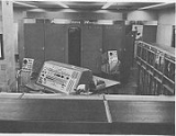
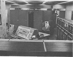
UNIVAC II
Encyclopedia
UNIVAC I
The UNIVAC I was the first commercial computer produced in the United States. It was designed principally by J. Presper Eckert and John Mauchly, the inventors of the ENIAC...
that UNIVAC
UNIVAC
UNIVAC is the name of a business unit and division of the Remington Rand company formed by the 1950 purchase of the Eckert-Mauchly Computer Corporation, founded four years earlier by ENIAC inventors J. Presper Eckert and John Mauchly, and the associated line of computers which continues to this day...
first delivered in 1958. The improvements included core memory of 2000 to 10000 words, UNISERVO II tape drives which could use either the old UNIVAC I metal tapes or the new PET tapes
PET film (biaxially oriented)
BoPET is a polyester film made from stretched polyethylene terephthalate and is used for its high tensile strength, chemical and dimensional stability, transparency, reflectivity, gas and aroma barrier properties and electrical insulation.A variety of companies manufacture boPET and other...
, and some of the circuits were transistorized
Transistor computer
A transistor computer is a computer which uses discrete transistors instead of vacuum tubes. The "first generation" of electronic computers used vacuum tubes, which generated large amounts of heat, were bulky, and were unreliable. A "second generation" of computers, through the late 1950s and...
(although it was still a vacuum tube
Vacuum tube
In electronics, a vacuum tube, electron tube , or thermionic valve , reduced to simply "tube" or "valve" in everyday parlance, is a device that relies on the flow of electric current through a vacuum...
computer). It was fully compatible with existing UNIVAC I programs for both code and data.
Circuit elements of entire system
| Tubes | 5,200 |
| Tube types | 20 |
| Crystal diodes | 18,000 |
| Magnetic cores | 184,000 |
| Transistors | 1,200 |
| Separate cabinets | 4 |
Above figures are approximate and do not include input-output devices.
Programming and numerical system
| Internal number system | Binary coded decimal |
| Decimal digits/word | 12 |
| Decimal digits/instruction | 6 |
| Instructions per word | 2 |
| Instructions decoded | 54 |
| Instructions used | 54 |
| Arithmetic system | Fixed point |
| Instruction type | One address |
| Number range between | -1 and +1 |
Decimal point occurs at the right of the sign digit.
Arithmetic unit
| Construction | Vacuum tubes |
| Arithmetic mode | Serial |
| Timing | Synchronous |
| Operation | Sequential |
| Including Storage Access (Microsec) | Excluding Storage Access (Microsec) | |
| Addition | 160 | 120 |
| Multiplication | 1,720 | 1,680 |
| Division | 3,030 | 2,990 |
Addition, subtraction, and multiplication times given below include reading and executing the instruction. The time includes formation of the result in the accumulator. All instructions, however are performed at minimum latency rates.
| Average Operating Speeds in Microseconds | |
| Addition or Subtraction | 200 (11-digit numbers) |
| Multiplication | 1,900 (11-digit numbers) |
| Division | 3,700 (11-digit numbers) |
| Comparison | 200 (12-digit numbers) |
| Transfer (Memory to Register or vice versa) | 40/word + 80/instruction |
Magnetic core
| Capacity | 10,000 words; 120,000 characters |
| Memory Locations | 0000 - 1999 |
| Access time | Zero (Memory references begin during "Time Out") |
| Basic Cycle | 20 microseconds |
| Construction | 42 separate magnetic core planes, each one a rectangle 50 cores wide and 80 cores long. |
All users utilize a 2,000 word 24,000 digit, magnetic core storage unit. Each of the planes is divided into two sections of 50 by 40 cores, making 2,000 cores in each section. Each section contains one core - for one binary position (bit) - of every one of the 2,000 words. The same relative binary position of the other half-word is held in a core in the same physical location in the other section of the plane. Thus each plane contains two binary positions in each of 2,000 words; the first and 43rd, for example, or the 9th and 52nd. Physically the memory is a rectangular prism 7¼ inches × 10 inches × 12¾ inches.
A memory location thus always implies two cores in all 42 planes. The two cores are determined by the intersection of one column of fifty possible columns with two rows of the 80 possible rows. One row is in each section of the plane. All 42 planes are used twice for each word.
Associated with the memory is a half-word insertion register of 42-bit capacity. Each bit is temporarily stored in a magnetic core of this register during a memory reference. Each of these register cores is associated with one of the 42 memory planes. To write into the memory, the first half of the word is placed in the insertion register and the address selector alerts the appropriate column and the proper row of the top section in each of the 42 planes. At the appropriate instant the information is transferred from each core of the insertion register to the selected core in the corresponding plane of the memory. 42 pulse times later, the second half word has been placed in the insertion register and the process is repeated in the lower section of the memory. Read-outs are accomplished in a reverse manner. The speed of the memory has been adjusted to the speed of the arithmetic portion of the Univac which permits the transfer into or out of the memory of 12 characters in 40 microseconds. Word pulses flow from or to the high speed bus and the insertion register via a mechanism which converts from serial to parallel and vice versa, in 42 bit modules.
Checking features
Checking Circuits. Whenever feasible, registers and other circuits appear in duplicate. Their contents are continuously compared so that inconsistencies between the data in the identical units give an indication of faulty operation, and stall the computer. At this point, the instruction may be repeated. The pulse code used in the Univac System is so designed that all characters contain an odd number of pulses. At several strategic points within Univac, every character is checked for an odd number of pulses. An indication is given whenever an even number of pulses is detected, and the computer stalls. Other types of checking circuits cause Univac to stall when other types of errors occur.An error occurs if reference to a non-existent memory address is attempted.
An odd-even error in the transfer rI to rM will result in a transfer stop and the location of the error (rI address) will be indicated. The 720 character count will be displayed on a modulus 100 counter.
"All ones" checker. In addition to the parity bits check on the high speed bus, a second checker establishes that the invalid "all ones" character is not inadvertently created by a system fault. Input and output checkers also detect the invalid "all ones" character.
Built-in checking features are contained in the Card-to-Tape Converter, the Tape-to-Card Converter and the High Speed Printer.
Fusing. Univac is completely fused
Fuse (electrical)
In electronics and electrical engineering, a fuse is a type of low resistance resistor that acts as a sacrificial device to provide overcurrent protection, of either the load or source circuit...
in order that faults may be isolated. Each bay has its own set of fuses in addition to main fuses on all DC and AC potentials. If a fuse blows, power is shut off and an indicator circuit shows in which bay the blown fuse is located, and a "flag" indicates the specific fuse.
Voltage Monitoring. An automatic voltage monitoring system continuously monitors all critical DC potentials giving an alarm if any moves outside the prescribed limits.