

TXE
Encyclopedia
TXE, which stands for Telephone eXchange Electronic, was the designation given to a family of telephone exchanges developed by the British General Post Office (GPO), now BT
, designed to replace the ageing Strowger
systems.
When World War II ended, the UK telephone exchange suppliers supported the GPO’s decision to stay with Strowger until a viable electronic system became available. The GPO largely did this to protect their success in the export market, but it actually had the effect of ultimately destroying it. This allowed competitors to develop their own improved switching systems ahead of the GPO. In 1960 the situation rapidly changed when the Australian PO rejected a system from a consortium of British manufacturers who offered a register-controlled version of a motor-uniselector system in favour of a crossbar
system from the Swedish firm of Ericsson
. Suddenly the rules had changed and the race was on to develop an electronic telephone exchange that could operate with the current GPO Telephones
used in the UK, including shared service
.
MBE
, employed at the GPO, had been working on VF (Voice Frequency) signalling, using valves, and this had led him to realise that valves could be very reliable if not switched on and off. This gave him the confidence during the War to build the world's first digital computer called Colossus
at Bletchley Park
. This computer used about a thousand valves and was a major factor in helping British Intelligence to break the German codes, though details of this were only released in 2000.http://news.zdnet.co.uk/security/0,1000000189,2081733,00.htm After the War, the success of Colossus encouraged him to contemplate the possibility of telephone exchanges each using tens of thousands of valves. He was told that this was impossible and he could not say he had already done it with Colossus because he was bound by the official secrets act. However a fully electronic prototype Time Division Multiplex
Model Exchange was constructed at the Post Office Research Station
at Dollis Hill
and then an experimental TDM exchange system was built and tested at Highgate Wood
, North London in 1962 but it was found to be beyond the technology of the time : the solid state switching worked well, but the analogue transmission (which had worked on the short cable runs of a laboratory model at Dollis Hill) was too noisy for public service on the long cable runs of a large exchange. However, the principles would be used later, as transmission became digital, in the development of digital exchanges the world over including System X
.
Siemens Brothers Ltd (later taken over by Associated Electrical Industries
Ltd who renamed each section accordingly e.g. AEI Telecoms) had set up an electronic switching lab at Blackheath in London. This lab was headed by John Flood, who had been a founder member of Tommy Flowers' electronic switching team at Dollis Hill. In the Siemens team was an engineer called Jim Warman
, who was probably the most talented switching system design engineer of that generation. It was his trunking ideas (sectionalisation, serial trunking, line scanning, route choice, repeat attempt etc.), which were to be central to the development of the British TXE exchanges.
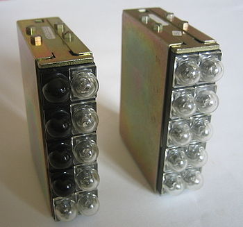
Following the failure to win major contracts in Australia in 1960 and the subsequent failure of Highgate Wood, it was necessary for the British manufacturers to come up with something different. L M Ericsson of Sweden had 20 years of experience of manufacturing the crossbar system and reducing its cost, so there was no point in trying to compete with them. (Plessy Telecommunications, a subsidiary company of The Plessey Company, took a different view and continued to urge the GPO to adopt crossbar.) At this time, in the USA, Bell Labs were developing a system based on electronically-controlled reed relay
s and this looked promising. One of Ericsson's marketing points for crossbar was that it used precious-metal contacts, but reed-relays would be even better as their precious metal contacts were hermetically sealed. Also their very short operating and release times (<1ms) made them ideal for electronic control and these reed-electronic exchanges were considered to be the most practical switching system to proceed with at the time and electronic enough, until a truly electronic system could be developed, although Tommy Flowers did not approve as he advocated going straight to a digital system.
The manager at AEI (W G Patterson) decided that reed-electronic space-division switching was the way to go and it was then that the term 'TXE'(Telephone Exchange Electronic) was coined, even although the reed relays themselves were not regarded as electronic components.
A much bigger team was needed to undertake the detailed development and AEI persuaded AT&E and STC to join them in the work. The initial result of their work was a prototype system called TXE1.
on the site of the former Lake House in Lake Street. This exchange type was developed by three members of the Joint Electronic Research Committee, JERC, which was formed in 1956 and lasted until 1969. This consisted of the British Post Office (GPO
), Siemens Brothers & Co Ltd (shortly to be part of AEI
, who were subsequently merged with GEC in the early 60s), Automatic Telephone & Electric Co. Ltd (known as AT&E and merged with Plessey
in 1961), the British company Ericsson Telephones Ltd (also merged with Plessey in 1961) - see http://web.ukonline.co.uk/freshwater/histatm.htm), General Electric Co. (GEC), and Standard Telephones & Cables Ltd. (STC
). The three members of the JERC who actually built the exchange were STC, AEI and AT&E. STC built the common control, AEI the switching, line scanning and test console, whilst AT&E took care of the dialling capturing equipment (Registers) and the Outgoing Junctions. The actual development of the TXE1 started around 1963, and went into service in 1968. There were models of the AEI equipment at Blackheath, London and of the ATE equipment at Edge Lane, Liverpool. AEI actually called TXE1 their REX (Reed Electronic Exchanges)
An equipment practice was needed and it was realised that a matrix of reed relays could be about the same size as a crossbar switch. Therefore the equipment practice of AT&E's crossbar system was adopted for the TXE1 apart from the STC common control who had their own equipment practice. Also, Hivac (then the only UK manufacturer of reed inserts) was an AT&E subsidiary. The STC common control consisted of 14 racks and made up a complete suite of the exchange. It was made entirely from discrete components as Integrated circuit
s were not yet in common use. There was much discussion by all contractors as to whether at the time there was a reliable connector so as to provide the ability to withdraw and replace units. STC decided to have the units withdraw and AT&E did not. It turned out that the connectors were reliable and STC had a great advantage in fault finding. It also allowed the STC engineers to place a suspect faulty unit in an outrigger so it could be tested in situ.
.
.
One of the jobs of the Common Control was to decide which was the best connection to be used through the switching network and this part was called the Route Choice. The Interrogators would return the available paths and the Route Choice would make a choice and tell the Markers to mark that route.
 .
.
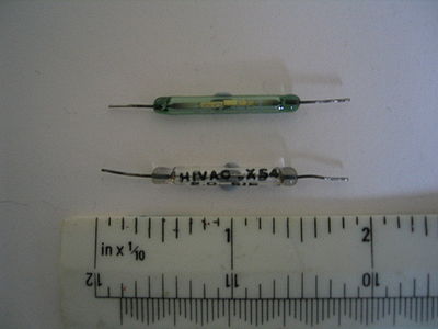
The exchange used reed relay
s as the switching medium, and the reeds themselves were approximately 3 inches in length and the only ones available. TXE2 exchanges would later on use reeds that were half this length. It had multi-stage switching divided into A, B and C switches and there were devices called links to connect the paths together. A typical local call would go ABC Link CBA. There were two types of links: ones with transmission bridges for local calls and others with no bridges for the outgoing junction calls. The bridges for the latter were contained within the outgoing junction units.
.
The exchange had some advanced features at the time, i.e. tone dialling was an option as opposed to pulse dialling, with no post-dialling delay for own exchange calls. It also had the ability to detect a switching failure and go for a repeat attempt without the subscriber being aware of it. Any repeat attempts were printed on a standard teleprinter. It had a futuristic test console, which monitored all the calls on a digital display.
A new approach to the inter rack cabling was taken. A ceiling was built above the top of the racks, creating a cable loft. The cables were just pushed through holes in the cable loft and taken to where they were going by the shortest route. The result was a complete mess of a cable loft, but all cables were labelled; it was quicker and easier than the normal way of lacing all the cables. The exchange was housed in a prototype K type single story building having a special provision reinforced ceiling for the overhead cabling already mentioned. The construction included thermal insulation panels and double-glazing to minimise heat loss and heating was by under floor electrical heaters operated on off-peak supplies. Ventilation arrangements were by eight ventilating units each handling 600 cu. ft. per min and a series of "hit and miss" type louvres above the windows on each side of the building provided outlets for heated air.
.
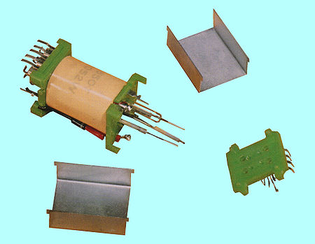
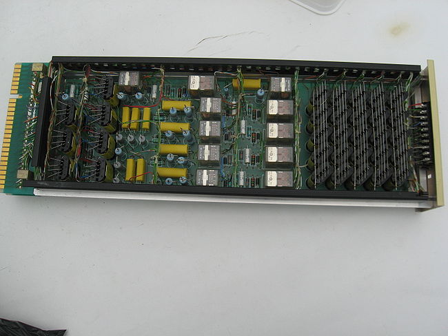
A novel but subsequently disastrous feature designed by Bell Antwerp was used to hold the subscriber’s Class of Service information i.e. PBX, Shared Service, TOS etc. This was a capacitor store and it held information on a thin plastic strip; into which could be inserted up to 10 little copper squares which had a capacitance of 10 pico farad. The thin plastic strip was then inserted into the Data Store rack at the position representing the directory number. This can be seen in the photograph together with some plastic strips hanging by wire. Hanging the strips by wire was a common practice for subscribers who were constantly changing their Class of Service, i.e. being made TOS. This information was then pulsed by the STC common control Translator and appropriate action taken. STC had enormous trouble getting it to work, which caused a delay to the whole exchange. In the end the problem turned out to be cable interference requiring substantial re-cabling. It was replaced by a threaded-core store called Dimond Rings in TXE3, TXE4 and TXE2, which were extremely reliable.
.
The AT&E Registers looked after all the dialling and there were three sorts of Registers:loop-disconnect
, MF
(later called DTMF), and incoming. The local Registers (loop-disconnect and MF) took care of own-exchange and outgoing calls, while the incoming Registers dealt with calls coming into the exchange. A local Register would provide dial tone to the subscriber, wait for the first dialled digit, and then apply to the Translator to see what action was required. The Translator could decide by the first digit if it was a local call and if it was it would instruct the Register to come back when it had all the digits. If it was not a local call and therefore to be routed out of the exchange, then it would tell the Register to come back with each digit until it could decide the routing, as not all calls went to the GSC (Group Switching Centre) as there was AAR (Alternative Available Routing). Once the routing had been decided and digits passed on, the Register was free to take another call.
The MF senders/receivers were used when an MF subscriber initiated a call. They were set up to the subscribers line and switching network to an MF register, they converted the MF tones to pulses for the registers to store. They used the X, Y and auxiliary switching planes.
Incoming Registers used a time-shared electronic dial path (TDM
) to transfer pulsing information from the incoming junction to the Incoming Register. This feature was necessary to ensure that no pulsing information was lost.
The Registers were made entirely from discrete components. The exchange had about 20 Local Registers and 12 Incoming Registers, each Register containing nine double units, which were hinged and could be lowered for easier access. These units unlike the common control were hard wired. However, a unit could be changed by breaking straps at the rear and then rewiring them, but it was a lengthy process taking about an hour to change just one unit on one Register. A subscriber was connected to the Local Register using the normal reed switching as the Local Registers were connected to the C switches. However, they communicated directly to the common control Translator via hard wiring.
The Translator was a complete rack of the common control (in fact rack 12) and its job as the title implies was to translate information and then give the appropriate action to the required part of the exchange.
In the event of a cable breakdown or other similar event which may result in permanent loop
s on subscribers lines, after a predetermined time the Register would be forcibly released and the subscriber put into a parked condition. This was possible because each subscriber had a dual armature line relay and in the parked condition the low current armature was operated but the other not. The scanners would ignore any park condition.
The scanners were provided by AEI and as the name implies scanned the subscribers seeking out the ones that had initiated a calling condition. They also detected subscribers in a “parked” condition. The scanners were mounted the racks of the associated switching units and fed back information so that a Register could be switched to the subscriber to provide dial tone.
The exchange was capable of dealing with 10,000 subscribers but it started out with a capacity of 3,000 subscribers, 152 incoming junctions and 166 outgoing junctions and plans were made to double the subscriber capacity this but this never happened. Tracing of calls within the exchange was instantly displayed digitally on the Test Console.
Occasionally the call trace did not work but the engineers worked out a way of manually tracing a call. What they did was to buy a little compass and glue a piece of magnetic ferrite on the side to pull the compass needle away from North. They would then run this compass along outside of the reed relays and when a relay was operated the needle would move back to North. This was repeated over several sets of the switching path until the trace was complete.
AT&E and STC created testers so that parts of the exchange could be taken out of service and the testers connected to these parts. The testers then simulated the signals that the exchange would send to it, and in this way individual parts of the exchange could be tested.
The Out Going (O/G) Junctions were provided by AT&E, and yet again were made of discrete components. There were three O/G junctions per shelf and they could be busied by using the keys that can be seen in the photograph.
There was an interesting opportunity using the three contractors as to how the different parts of the exchange were to be connected together, and much time was spent on this.
A display was created next to the test console, which gave a visual indication of the traffic flowing through the exchange, and it was named the Hubblemeter after the instigator Ray Hubble.
The TXE1 required power supplies of -18 V, +50 V and -50 V DC. These were provided in the usual manner by lead acid rechargeable batteries charged from the 240 Volts AC mains supply and backed up by a diesel generator in case of mains power failure.
The exchange went into service in 1968 and proved reasonably reliable although it did have a few outages. Most of these were caused in the Common Control area. The common control equipment was divided into functional units and each unit was duplicated an A side and a B side and each section was isolated by means of reed relays. Under either fault conditions or manual control or the predetermined time, the unit indicated would change over to its partner. The changeover of the relays was controlled by a series of reed relays whose reed inserts were wetted with mercury. Periodically over some weeks, the mercury would migrate to the point of contact of the blades leaving a mercuric bead giving “ON” and both A and B sides into service. The confusion generated caused the exchange to be isolated.
There were also some problems with the ASY63 transistors that had Nickel Iron connecting wires and would not take the solder causing dry joints to the circuit cards. This happened over all sections of the electronic equipment in the common control area. The remedy to this problem was to re-solder connections with a solder with a stronger flux.
It was withdrawn from service in 1977 when it was replaced by a TXE4. Unfortunately the whole exchange was then scrapped and allegedly the scrap men put a sledgehammer through that lovely console.
exchanges - usually UAX13s. The first TXE2 was installed at Ambergate
near Matlock in Derbyshire and it opened on the 15th December 1966. Ambergate was chosen because it was a suitable small exchange (200 lines) which was some 20 miles from the Plessey factory at Beeston, Nottingham. The manual exchange which it replaced was kept on standby for several months, until sufficient operational confidence was developed in the TXE2. Although the system had been developed by Plessey, for security (and perhaps in an attempt to drive prices down) the GPO had insisted on competitive tendering for the TXE2 exchanges. Production contracts were awarded simultaneously to Plessey, STC and GEC, and the distribution of the three manufacturers products into the field was done on an apparently random basis. Some 2-3000 TXE2s went into service with the GPO, the last one being withdrawn from service on June 23 1995.
The Pentex system, which evolved beyond TXE2, was exported to over 30 countries and was largely responsible for Plessey winning the Queen's Award for Exports in 1978.
 In the summer of 2005 a demonstration rack of TXE2 equipment was transferred to the Connected Earth collection at Milton Keynes Museum. See http://www.connected-earth.com/Daysout/MiltonKeynesMuseum/index.htm
There is a working TXE2 at Avoncroft Museum. It can be used to make calls within the museum. For a virtual tour inside this Plessey mobile TXE2 (or MXE2, as they were called) at Avoncroft Museum see http://www.connected-earth.com/Daysout/AvoncroftMuseumofHistoricBuildings/Virtualtour/pano009.htm
A few details about the MXE2s are given at http://www.thg.org.uk/mndx/index.htm.
Many of the MXE2s ended up in Northern Ireland. Only one of these ever had to be used 'in anger'. This was at Castlewellan about 1990, when the exchange was blown up by terrorists. The typical set-up time for an MXE2 was about 6 weeks, but at Castlewellan full telephone service was restored using an MXE2 (and the additional use of a mobile transmission unit designed by Northern Ireland staff) within one week of the bombing. It did however take a lot of subsequent work by the switch maintenance Technical Officers to get the exchange up to an acceptable standard of service, as it had been standing idle for several years.
The photograph on the left shows several racks inside Ambergate Exchange. Although the first TXE2-type exchange to go into public service, it actually consisted of Plessy pre-production equipment, called Pentex. The clumsy large handles on the front of the slide-in units are the obvious distinguishing feature. It is also apparent that the racks and units are painted in battleship grey. The change from this to the 'light straw' colour of all subsequent exchanges (including all other TXE2s) was a significant change in an organisation where exchange equipment had been battleship grey for as long as any telephone engineer could remember.
design, isolation (inability of the exchange to set up calls) of the entire exchange was always a possibility and very occasionally happened. This potential weakness had been at least partially recognised in the design of the exchange type, so the most critical common control units were split into three sections and each section was duplicated into an A-side and a B-side. In the event of the equipment detecting a serious fault in one of the side-conscious units, all the units in that section were locked onto the side which was giving good service and a prompt alarm was sent to a manned centre to indicate that the exchange needed urgent attention.
In normal service the exchange automatically changed all three sections from one side to the other every 8 minutes. If Call Control detected 8 failures to set up calls within that 8 minutes, then it force-changed all the side-conscious units onto the other side, locked that side in service and raised a prompt alarm. In periods of very low traffic, there would typically be fewer than 8 call set-up attempts on the exchange in 8 minutes and this would have prevented the above security system from working. The exchange was therefore provided with an automatic Test Call Unit, which originated a test call every 30 seconds. As well as thus enabling Call Control to detect 8 failures in less than 8 minutes (if all call-attempts were failing), the Test Call would raise its own prompt alarm if it detected 31 sequential call-attempt failures, indicating that neither security side of the exchange was able to connect calls.
The photograph below right shows the Alarm Indicating Panel at the only remaining working TXE2, at Avoncroft Museum. The red lamps show that all three sections are alarmed. The 8-minute changeover will therefore have been suspended and the white lamps show that all three security sections are locked on to side B. If a maintenance man was called to an exchange because of an extended prompt alarm, this panel would generally be his first port of call in order to see what equipment was in an alarmed state.
As a further security measure, if the first attempt to set-up a path to a Register failed, so that, on an outgoing call, the customer did not get dial-tone, the exchange recognised the failure, stored the details of the equipment in use on the failed call and automatically made a second attempt, using different equipment. This happened so quickly (about 50 milliseconds) that, if the second attempt was successful, the customer would not have been aware of the failed first attempt to get dial-tone.
A security weakness on the rural Strowger exchanges (UAX 13s and smaller) had been the electrical power supply. If the main feed went down, the exchanges relied on back-up batteries, but these could only keep the exchange going for a few hours and after that, service was lost across the whole exchange to typically several hundred customers. The TXE2s were much better equipped. They had a separate power room, itself often bigger than the entire UAX 13, in which, as well as back-up batteries, there was a stand-by diesel generator. This started automatically in the event of a power cut and could keep the exchange going for days. Isolations due to power cuts therefore became a thing of the past, but at considerable initial capital cost.
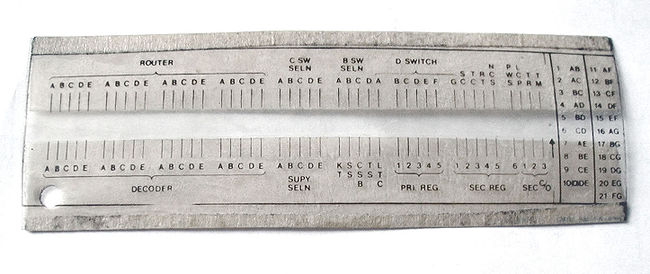 As a maintenance aid, the exchange was equipped with a Maintenance Data Recorder (MDR). This had a rather primitive printer, which displayed the identities of equipment in use at the time that the exchange had detected a call failure. For example, in the event of a successful repeat attempt to provide dial-tone, the MDR would print. If the repeat attempt failed, then the MDR would print twice in quick succession, giving details of the equipment in use on both the failed paths. The prints were not easy to read. All that emerged were short burn marks on the special paper in up to 45 different places in each of two rows. It was necessary to hold a plastic graticule (see picture at end of this section) over the paper to find out what the presence of each burn mark indicated. If more than 8 call failures were detected in less than 8 minutes, then the critical common control units would be forced to change from the side in service (A or B) to the other side, the automatic 8-minute changeover would be suspended and a prompt alarm would be sent out.
The picture above of the TXE2 equipment in Hullbridge
Telephone Exchange gives a good impression of the inside of a typical early TXE2. They were quite spacious (very spacious compared with the Strowger
UAX13 which most of them replaced) and with the cleaner generally living locally and taking a pride in the job, they were usually kept very clean and tidy, as in this example. The picture shows the Control Suite in a Plessey exchange. There would typically have been 5 or 6 suites, with plenty more floor space, to allow for growth.
All the TXE2-specific equipment was mounted on slide-in units, mainly single-width, but some double-width. There was a carefully structured holding of maintenance spare units. For those which were likely to be needed frequently or urgently in every exchange, such as a Subscribers Line Unit (a single unit containing the line relays and A-switches for 5 customers), a spare unit was held in every exchange. For those units for which a spare was likely to be needed less frequently or urgently, the spares were held at an Area centre serving perhaps 6-10 TXE2s of the same manufacture. Finally for those units for which a spare was likely to be needed seldom, the spare units were held Regionally. There were 10 Regions in BT at that time.
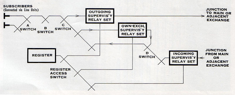
In TXE2s a call which terminated within the same exchange went through 7 switching stages, whereas a call going out to another exchange went through just 3 switching stages. The switches were designated as A, B, C and D (the paths were ABC for outgoing, ABCDCBA for internal and DCBA for incoming). The common control equipment consisted of B- and C-Switch Selectors, Supervisory Selectors (a Supervisory relay set stayed in-circuit throughout each call), Register Selectors, Registers and Call Control.
The most characteristic feature of the exchange's central control unit design was its mode of operation, a processing of all calls on a one-call-at-a-time basis. This meant that call set-up had to be accomplished in a very short period of time. In particular Call Control had to become free in less than the time of the inter-digital pause on calls incoming to the exchange. This time could be as low as 60 milliseconds. As the TXE2 call-set-up time was some 50 milliseconds, this design requirement was just met, but even so the overall capacity of the system was determined by the probability of an incoming call being delayed too long in its initial connection to a register.
The grade of service
in a TXE2 was dependent on the number of customers in an A-switch group, with access to just 25 A-B trunks. The normal standard on the earlier exchanges was 125 customers per A-switch group. If the A-switch group contained many busy PBX lines, then the number of customers might be reduced to 75. The earlier (Mark I and Mark II - the differences being slight) exchanges could handle up to 2000 customers. Later on Mark III TXE2s were able to handle up to 4000 customers and on these exchanges, where the average calling rate was sufficiently low, up to 250 customers would be in an A-switch group, still with access to just 25 A-B trunks.
The choice of the main type of memory used in the TXE2 (and the TXE4) was particularly characteristic of the general design philosophy, that the components used had to be of a technology that had been tested over many years. The choice thus went to the 'Dimond ring' type of memory, named after T.L.Dimond of Bell Laboratories, who invented them in 1945. They were large-diameter magnetic ferrite toroidal rings with solenoid windings, through which are threaded writing and reading wires. This set-up is shown fairly clearly in the picture (above) of the Ambergate Calling Number Generator and Class of Service racks. These racks gave the ability to convert a subscriber's directory number into an equipment location identity. This was a considerable innovation in British exchanges, since in Strowger exchanges the directory and equipment numbers had to be the same.
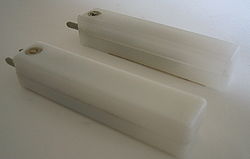
 The switching in TXE2s was carried out by reed relay
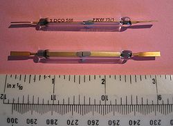
s and a typical TXE2 contained about 100,000 reeds. A 'reed' was actually two over-lapping ferromagnetic blades hermetically sealed within an inert-gas-filled glass capsule. The blades were gold-plated and separated by just a few thousandths of an inch. The reeds were fast in operation (about 1 millisecond), with a life expectancy of more than 10 million operations. The glass capsules were about an inch (25 mm) in length and about an eighth of an inch (3 mm) in diameter. Four reeds were generally present inside each relay coil, two for the speech-path, one for holding the path and one for metering. Switching with these reeds held out the prospect of much greater reliability compared with the Strowger system, where switching was carried out by base metal wipers moving through banks of metal contacts. The Strowger switches required routines to be carried out on them to clean the banks: they also required oiling and occasional adjustment. Reed relays required none of this. However, in practice, and particularly in the early years of the system's service, the performance of the reeds proved to be less good than had been expected.
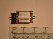
The picture (right) of a TXE2 Supervisory relay-set gives an idea of the technology involved. Designed in the 1960s, it consisted of discrete components mounted on circuit boards. These relay sets were of double width. On the face-plates there were two built-in lamps (for call-tracing and fault indication) and a block of test points, which gave test access to the circuits inside. Three "candles" can be seen protruding from units: these were simple indicator-bulbs which were used as required to show when the relay sets were in use. These "candles" or "busy indicators" were used throughout the exchange as part of fault-finding.
The TXE2-specific equipment was different in the TXE2s manufactured by Plessey, STC and GEC, so that spare equipment had to be held for each type of manufacturer. Importantly, each manufacturer made their own reed inserts (GEC's were actually made by one of their subsidiary companies, the Mazda Osram Valve Company) and their performance differed significantly in the first years of production.
 The picture below shows an STC SLU (Subscribers' Line Unit - in those days customers were always called subscribers, invariably shortened in conversation to 'subs'). It handled the traffic to and from 5 customers, and had 5 trunks going on to the B switches. There is therefore a 5X5 switching matrix of reed-relays, which constituted the A-switch. Note that the 4 reeds in each of these reed-relay were in-line, whereas in Plessey reed-relays the reeds were in a square formation. The SLU also contained 10 electro-mechanical relays, 2 for each line. They were the Line Relay (LR), which was operated when the customer picked up the handset and which generated the calling signal, and a K relay which gave the correct tones and prevented spurious calling conditions. These two relays both provided change-over contacts and therefore had to be electro-mechanical, because the reed-relays only gave make-break contacts. The face-plate of the unit is to the right: at the other end one can see the edge connector
. It was feared that this type of connector would cause problems after a relatively low number of removal/re-insertion operations, but in practice they proved to be more than adequately robust.
 In the early (around 1969) Plessey exchanges a significantly high proportion of the reed-inserts were contaminated with a high-resistance film and were prone to giving an intermittently high-resistance contact. If this occurred in one of the common-control areas of the exchange it could, and did (despite the A- and B-sides described above), give rise to the exchange becoming isolated (being unable to set up any calls) for perhaps several hours in a worst case. These faults were very difficult to locate and in the end the problems were only resolved by a fairly substantial re-reeding programme carried out on the common-control units of the early Plessey exchanges.
The STC reeds proved to be more reliable, but, if they failed, they tended to stick or fail short-circuit. This was also a cause of isolations early on, but a simple modification restricted the most serious failure to a small part of the exchange. The GEC/MOV reeds proved to be the most reliable of all.
Once the teething troubles had been largely dealt with, which was not until about 1974, the TXE2s realised more of their expected benefits and it was eventually not uncommon for one Technical Officer to maintain the operation of three of these exchanges, serving perhaps some 5-6000 customers in total.
During the development of the TXE3 it became apparent that the system would be too expensive for the competitive export market, so AEI split its team into two: one to do whatever the BPO wanted and the other to produce a reduced version for export. The trial was started in April 1968 and the model worked very well at Armour House and the BPO ordered the first half dozen exchanges. Jim Warman moved his team back from Blackheath to Woolwich to start a new department with its own manufacturing and marketing. The equipment for the first exchange had been manufactured with a 9600 capacity and was being installed on site at Royal exchange in London in 1968 when GEC made a takeover bid for AEI who were in financial difficulties brought about by the development costs of TXE1 and TXE3. The takeover bid was and GEC decided, unbelievably, that they preferred the crossbar system to TXE3 and promptly cancelled the contract to supply TXE3 to the BPO. Royal first exchange was dismantled before its installation had been completed and all the TXE3 equipment was broken up and supplied to universities for observation.
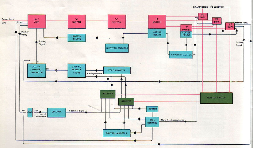
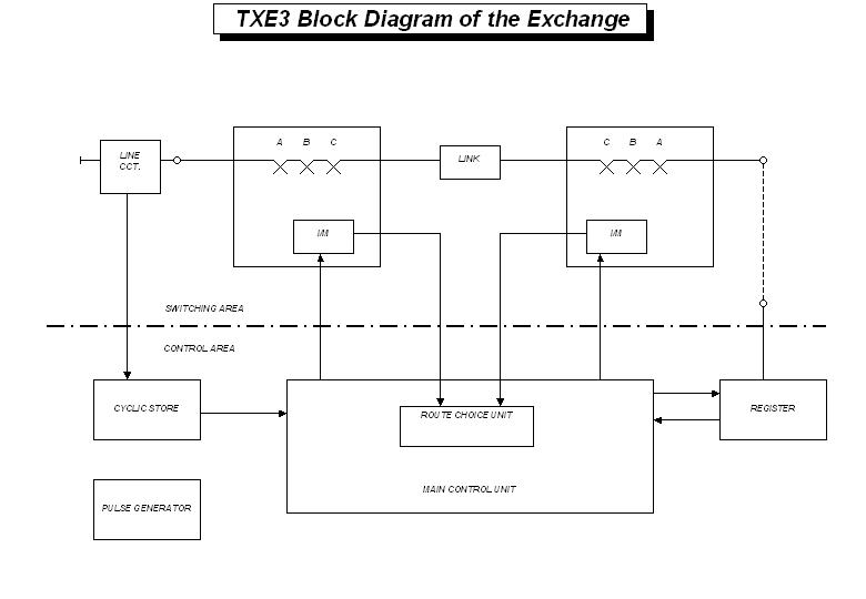
(1) Peripheral equipment comprising subscribers' line circuits, junction terminations and other units providing a variety of special functions such as coin and fee checking on coin box calls.
(2) A switching area through which connections are established between peripheral equipment. It is arranged to give three stages of switching on either side of centrally located link circuits
(3) A control area, that received information from peripheral equipment and the switching area, and processed this with data held in its own store to determine the actions required. It issued instructions to the other areas and checks their successful completion, making second attempts if necessary.
The control area was called the Main Control Unit(MCU) and there were two provided on the model for security although a maximum of 12 could have been provided. Each MCU was capable of handling approximately 6,000 instructions per hour. The MCU operated in accordance with an instruction program stored in the form of a number of wires threading a bank of magnetic cores. Changes in the operating sequence can be obtained by program changes involving the re-threading of a number of wires in the store instead of by widespread re-wiring within and between a multitude of separate units.
Line scanning circuits sequentially examined the state of each line, junctions and so on by means of a pulse many times a second and immediately after each pulse a data store (the Cyclic Store) offered the MCU permanent information relating to the line. When a calling condition was detected, the scanning pulse was passed to the MCU indicating to it that a new call had to be set up and busying it temporarily to further calls. As the first steps in dealing with the new call the MCU recorded the directory number and class of service (shared service, PABX line, incoming junction register, TOS and so on) information offered by the Cyclic Store and allocates one of its associated group of up to 30 registers. The registers were connected to peripheral terminals of the switching network, in the same way as subscribers' lines, junction circuits and other units and the MCU proceeded to issue instructions to the network to connect the subscriber and register terminals.
The switching network was composed of reed relay cross-points arranged to give three (A, B and C) stages of switching on either side of a number of linking circuits. The A-stage switches concentrate traffic from the peripheral terminals on to B-C-stage arrays, which are internally connected to provide full accessibility between every B-switch terminal and every C-switch terminal of the array. A simple switch enabling two subscribers to be connected to two others can be constructed, but extending this to larger sizes becomes increasingly uneconomic. Nevertheless, by splitting the network into two stages, considerable economy could be affected.
To connect the allotted registers to the calling line, the MCU asked the interrogator-markers to identify all free paths from the subscriber to the central, "through" type, links and from the register to the links. This information was returned to the Route Choice Unit, which then identified those link circuits, which were available to both peripheral terminals, and selected the most suitable, according to predetermined rules chosen to make maximum use of the network. Its decision was signalled back to the MCU which then instructed the interrogator-markers to mark the chosen pair of paths, starting from the link out through the C, B and A stages to the subscriber, and then from the other side of the same link, through C, B and A-stages to the register.
 The register then checked the connection to the subscriber and sent dial tone. Normally, the whole process took about one-fifth of a second, less than the time required for the subscriber to lift the handset to his ear. The MCU, having completed its immediate tasks for this call, was free to deal with other demands. It retained a record of the calling equipment number against the identity of the register and notes the stage, which had been reached in the progress of the call.
The subscriber dialled the required number and as each digit was received it was stored in electronic circuits within the register, which will call for the MCU after each digit and ask for instructions. Until sufficient digits have been received to determine the outgoing route from the exchange, the instruction will be "apply again after the next digit" and the MCU returned to serving other demands.
When sufficient digits had been received, the MCU would have been able to determine the required path through the exchange, the routing digits to be sent (if an outgoing call is indicated), and which of the received digits have to be repeated forward. It would advise the register accordingly and then set the paths necessary to allow the register to signal forward and finally extend the caller to the required number or junction.
On calls which terminated on the exchange a transmission bridge and supervisory circuit needed to be introduced within the switching network. This was done by employing a "bridge link" in the final connection. To allow metering on own-exchange calls these links also contain local call timing elements which pulse the P-wire in the desired "X" or "Y" phase at the appropriate times. "X" and "Y" phases were only required to support the metering for shared service subscribers, which has long since disappeared thankfully.
Similar procedures would be followed for any other type of call. In every case the MCU would decide, in accordance with its program instructions, what connection pattern was appropriate in the circumstances indicated and issue orders for setting the paths.
Within each MCU information was handled in a "two-out-of-five" code which enabled errors to be detected, and the output of the program store was duplicated to give additional protection.
The TXE 3 model gave satisfactory service and the experience gained from the model confirmed the validity of the basic design and led to the development of the TXE4.
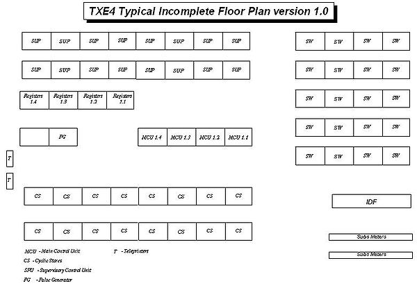
 The TXE4 was a development of the TXE3 system and catered for up to 40,000 subscribers with over 5,000 erlangs of bothway traffic and was normally staffed by several Technical Officers (TO). This was developed purely by STC
to a specification from the GPO. It was built at the STC Southgate factory in north London and used reed relays as the switching medium which proved reliable in service. Later a small amount of exchanges were also manufactured by PLessy and GEC. It had a programmable common control called the Main Control Unit (MCU) and each exchange had at least three MCUs for security and a maximum of twenty, but in theory could operate with just one. It had a unit called the Supervisory Control Unit, which took control of the calls from information supplied to it by the MCU.
The man responsible for marketing strategy of STC at the time, Ken Frost said “We took a chance on going into TXE4. In the first place without any firm commitment from the Post Office. And then we got into the great modernisation programme, in which we argued for modernisation with TXE4 while Plessey and GEC made their case for crossbar with some electronic control on it. The Post Office decision was for TXE4”.
To prove the enhancements of TXE4 over the TXE3 a test bed trial installation was installed in Tudor exchange in North London in 1969. After a successful two year trial a contract was placed with STC for the provision of £15million of TXE4 equipment in June 1971.
The first actual production TXE4 was installed in 1973 at Rectory, a suburb of Birmingham brought into service on the 28th February 1976. TXE4 is sometimes is known as TXE4RD where the RD stood for Rectory Design. Rectory opened with 4300 subscribers and had a maximum capacity of 8000. In 1983 there were 350 TXE4s in service serving 4 million customers. The last TXE4s were taken out of service (at Selby, Yorkshire and Leigh-on-Sea, Essex) on March 11 1998.
Subscriber information was programmed into the exchange in racks called cyclic stores which used PTFE wire threaded through magnetic cores known as 'Dimond ring'(see TXE2 section for more information). The information stored was the Class of Service (COS) i.e. PBX, CCB (payphone
) or single line, followed by the directory number. The subscribers derived an equipment number from the position on the cyclic store rack. This was a six-digit number and referred to as the MUCKBL, which describes to the exchange where this is. In some parts of the exchange equipment the equipment number was used as BUMCLK and this was used by engineers as a pseudo swear word. When a subscriber lifted their handset it sent a pulse down this wire, which was picked up by a 156 msec scanner, which initiated a path to be set up through the reed relays so the subscriber could be connected to a Register. This Register then returned dialling tone to the subscriber and dialling could commence.
The Registers were "owned" by the MCUs and each MCU had a maximum of 36 Registers. The MCU was responsible for looking after all of its Registers and deciding from the dialled information where the call was going to be routed. Once it decided this, it sent a command to the Interrogator/Markers to set up the required path and then moved on to the next task. Once the connection had been established, the SPU took care of the path and all the call metering tasks. The MCUs all had 36 Registers and had solid-state memory to hold the dialled digits from all the Registers and also had other storage to manipulate call set-up information.
There were three scan rates: 156ms for subscribers, 36ms for Registers and Outgoing Junctions, and 12ms for Incoming Junctions. The last of these was the quickest scan, to ensure that no pulses were lost from the incoming junctions.
As the exchange ran on timing pulses, unlike the TXE2 design, there was a Pulse Generator Rack, which provided them. The generator used a delay line oscillator of 166.7 kHz to produce a basic pulse of 6 microsecond’s duration and this was fed to 8 ring counters which then multiplied up the basic 6 microsecond pulses into the various pulse requirements. There were four generators, because of security reasons, and of the vital importance of these pulses. The exchange could still function if one generator was out of service.
A problem was discovered very late in the development of the TXE4 in that an equipment number could be threaded with the wrong directory number by mistake. Even worse it could be the directory number of another equipment number leading to multiple directory numbers. The exchange had no way of detecting this but the problem was solved in a very novel way.

 The MCU was run by a programme that was stored in 10 Slide in Units (SIU) located at the bottom of the MCU rack. These units were called MTWS, which stood for Miniature Threaded Wire Store which was a misnomer as there was nothing miniature about them. The MTWS was a matrix of eight by ten cores through which enamelled wire could be threaded. Each MTWS held 500 programming steps and so the whole exchange had to be run using 5000 steps, which was a remarkable feat. It was even more remarkable because it only used the first 8 MTWS as the last two were reserved for special routines.
The 5000 programming steps were named with the letters A-E and then three numbers e.g. B525. Each step consisted of 8 pieces of information and these were of value from 1 to 10 depending on what core the wire was threaded through. The first three digits told the MCU what program step to go to next e.g. 891 and the first letter being decided usually by a decision i.e. whether some information was present A=yes, B=no resulting in either A891 or B891. The next two pieces of information gave what the operation was e.g. 55 compare two pieces of information and the last three told the MCU where to store the result i.e. 020 put this information in MFS (Main Ferrite Store) 10(see next paragraph for more information). So the whole programme step would be 89155020. Each step took 12 microseconds to execute. This program, the software of the exchange, could easily be changed as developments and upgrades occurred throughout the life of the TXE4 design.
The MCU contained a non-volatile data store, which used core store. There were three types of data store, Main Ferrite Store (MFS), Special Ferrite Store (SFS) and Register Ferrite Store (RFS). The MFS was used by the MCU itself to hold data for various reasons and the SFS was used for manipulating data. An example of this was that SFS2 could take the data stored is positions 1-5 and swap them with data stored in positions 6-10. It can be seen from this that each store had 10 positions and each one could hold values from 1 to 10. Incidentally this was stored in 2 out of 5 code
. I.e. 11000 = 1, 10100=2, 01100=3. The RFS held data from each of the MCU’s associated registers e.g. dialled digits. There were 20 MFS, 4 SFS and up to 36 RFS.
The MCU was in control of setting up switching paths and it knew when a path had not been successful. In this case the MCU would instigate a repeat attempt to set a new path. The details of the failed path were sent to the printer.
The TXE4 had two standard Teleprinter
, which were used to give fault indications and other information. The difficulty of manually spotting trends brought an attempt to take the paper tape that the tele-printer produced, as well as the print, and automatically analyse it. It was called PATE4, which stood for Print Analysis TXE4 and was a software programme that read the paper tape looking for common fault patterns.
The TXE4 exchanges were designed for a Mean Time Between Failures (MTBF) of 50 years and, although this was never quite achieved, it could be argued that the design requirement had been met if you discounted human interventions!
Incomplete List of TXE4 Exchanges
TXE4A dispensed with Dimond rings and used solid state memory. This allowed for changes to exchange data i.e. customer information to be made by keyboard instead of by laboriously threading jumpers through Dimond rings.
The first TXE4A to enter service was Belgrave, Leicester on 28 February 1981. Altogether over 550 TXE4 and TXE4A exchanges were installed and they were around for over 20 years serving 8 million lines. During its life the TXE4/A system proved to be highly successful and reliable until eventually replaced by System X. The TXE4 era came to an end on the 11th March 1998 when Selby and Leigh-on-Sea were replaced by digital exchanges.
Incomplete List of TXE4A Exchanges
The system also had the capability to busy equipment and reset alarms remotely.
The cyclic store gates, where all the subscriber information was held, were replaced by solid state devices as phase 2 of the enhancement.
 TXE6 was an electronic common control exchange that was designed to extend Strowger
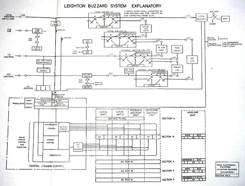
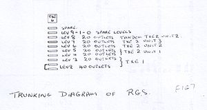
exchanges, and known as the Electronic Reed Selector System or Reed Group Selector(RGS). Only two were built: one in London and the other at Leighton Buzzard
. The one in London was moved and combined with the one at Leighton Buzzard, incidentally the Leighton Buzzard one was coloured light straw and the London one grey so when they were combined it was easy to tell where each unit came from.
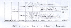 It was never used for its intended purpose but merely acted as the front end to incoming junction calls at Leighton Buzzard and directing them to the appropriate part of the exchange decided by the first dialled digit. As the name suggests it used reeds as its switching medium.
BT Group
BT Group plc is a global telecommunications services company headquartered in London, United Kingdom. It is one of the largest telecommunications services companies in the world and has operations in more than 170 countries. Through its BT Global Services division it is a major supplier of...
, designed to replace the ageing Strowger
Strowger switch
The Strowger switch, also known as Step-by-Step or SXS, is an early electromechanical telephone switching system invented by Almon Brown Strowger...
systems.
When World War II ended, the UK telephone exchange suppliers supported the GPO’s decision to stay with Strowger until a viable electronic system became available. The GPO largely did this to protect their success in the export market, but it actually had the effect of ultimately destroying it. This allowed competitors to develop their own improved switching systems ahead of the GPO. In 1960 the situation rapidly changed when the Australian PO rejected a system from a consortium of British manufacturers who offered a register-controlled version of a motor-uniselector system in favour of a crossbar
Crossbar switch
In electronics, a crossbar switch is a switch connecting multiple inputs to multiple outputs in a matrix manner....
system from the Swedish firm of Ericsson
Ericsson
Ericsson , one of Sweden's largest companies, is a provider of telecommunication and data communication systems, and related services, covering a range of technologies, including especially mobile networks...
. Suddenly the rules had changed and the race was on to develop an electronic telephone exchange that could operate with the current GPO Telephones
GPO telephones
The United Kingdom's General Post Office had a number of telephones that were provided by them for connection to their exchanges. Until 1982 the GPO had a monopoly on the provision of all telephones within the UK and so the range was limited...
used in the UK, including shared service
Party line (telephony)
In twentieth-century telephone systems, a party line is an arrangement in which two or more customers are connected directly to the same local loop. Prior to World War II in the United States, party lines were the primary way residential subscribers acquired local telephone service...
.
Introduction
Just before World War II, Tommy FlowersTommy Flowers
Thomas "Tommy" Harold Flowers, MBE was an English engineer. During World War II, Flowers designed Colossus, the world's first programmable electronic computer, to help solve encrypted German messages.-Early life:...
MBE
Order of the British Empire
The Most Excellent Order of the British Empire is an order of chivalry established on 4 June 1917 by George V of the United Kingdom. The Order comprises five classes in civil and military divisions...
, employed at the GPO, had been working on VF (Voice Frequency) signalling, using valves, and this had led him to realise that valves could be very reliable if not switched on and off. This gave him the confidence during the War to build the world's first digital computer called Colossus
Colossus computer
Not to be confused with the fictional computer of the same name in the movie Colossus: The Forbin Project.Colossus was the world's first electronic, digital, programmable computer. Colossus and its successors were used by British codebreakers to help read encrypted German messages during World War II...
at Bletchley Park
Bletchley Park
Bletchley Park is an estate located in the town of Bletchley, in Buckinghamshire, England, which currently houses the National Museum of Computing...
. This computer used about a thousand valves and was a major factor in helping British Intelligence to break the German codes, though details of this were only released in 2000.http://news.zdnet.co.uk/security/0,1000000189,2081733,00.htm After the War, the success of Colossus encouraged him to contemplate the possibility of telephone exchanges each using tens of thousands of valves. He was told that this was impossible and he could not say he had already done it with Colossus because he was bound by the official secrets act. However a fully electronic prototype Time Division Multiplex
Time-division multiplexing
Time-division multiplexing is a type of digital multiplexing in which two or more bit streams or signals are transferred apparently simultaneously as sub-channels in one communication channel, but are physically taking turns on the channel. The time domain is divided into several recurrent...
Model Exchange was constructed at the Post Office Research Station
Post Office Research Station
The Post Office Research Station at Dollis Hill, London, was first established in 1921 and opened by Prime Minister Ramsay MacDonald in 1933.In 1943 the world's first programmable electronic computer, Colossus Mark 1 was built by Tommy Flowers and his team, followed in 1944 and 1945 by nine...
at Dollis Hill
Dollis Hill
Dollis Hill is an area of north-west London. It lies close to Willesden, in the London Borough of Brent. As a result, Dollis Hill is sometimes referred as being part of Willesden, especially by the national press...
and then an experimental TDM exchange system was built and tested at Highgate Wood
Highgate Wood Telephone Exchange
The Highgate Wood Telephone Exchange was a telephone exchange built in the London suburb of Highgate Wood. It was the site of a trial for an electronic telephone exchange built by members from Joint Electronic Research Council , which was formed in 1956 and consisted of the British Post Office GPO,...
, North London in 1962 but it was found to be beyond the technology of the time : the solid state switching worked well, but the analogue transmission (which had worked on the short cable runs of a laboratory model at Dollis Hill) was too noisy for public service on the long cable runs of a large exchange. However, the principles would be used later, as transmission became digital, in the development of digital exchanges the world over including System X
System X (telephony)
System X was the name of the UK's first national digital telephone exchange system.-Development:System X was developed by the UK Post Office , GEC, Plessey, and Standard Telephones and Cables and first shown in public in 1979 at the Telecom 79 exhibition in Geneva Switzerland...
.
Siemens Brothers Ltd (later taken over by Associated Electrical Industries
Associated Electrical Industries
Associated Electrical Industries was a British holding company formed in 1928 through the merger of the British Thomson-Houston Company and Metropolitan-Vickers electrical engineering companies...
Ltd who renamed each section accordingly e.g. AEI Telecoms) had set up an electronic switching lab at Blackheath in London. This lab was headed by John Flood, who had been a founder member of Tommy Flowers' electronic switching team at Dollis Hill. In the Siemens team was an engineer called Jim Warman
Jim Warman
Bloomfield James Warman, who was known as Jim Warman and was a most gifted English electrical engineer. He was born at Westcombe Park in South London. During the Second World war he served in the REME....
, who was probably the most talented switching system design engineer of that generation. It was his trunking ideas (sectionalisation, serial trunking, line scanning, route choice, repeat attempt etc.), which were to be central to the development of the British TXE exchanges.
Following the failure to win major contracts in Australia in 1960 and the subsequent failure of Highgate Wood, it was necessary for the British manufacturers to come up with something different. L M Ericsson of Sweden had 20 years of experience of manufacturing the crossbar system and reducing its cost, so there was no point in trying to compete with them. (Plessy Telecommunications, a subsidiary company of The Plessey Company, took a different view and continued to urge the GPO to adopt crossbar.) At this time, in the USA, Bell Labs were developing a system based on electronically-controlled reed relay
Reed relay
A reed relay is a type of relay that uses an electromagnet to control one or more reed switches. The contacts are of magnetic material and the electromagnet acts directly on them without requiring an armature to move them...
s and this looked promising. One of Ericsson's marketing points for crossbar was that it used precious-metal contacts, but reed-relays would be even better as their precious metal contacts were hermetically sealed. Also their very short operating and release times (<1ms) made them ideal for electronic control and these reed-electronic exchanges were considered to be the most practical switching system to proceed with at the time and electronic enough, until a truly electronic system could be developed, although Tommy Flowers did not approve as he advocated going straight to a digital system.
The manager at AEI (W G Patterson) decided that reed-electronic space-division switching was the way to go and it was then that the term 'TXE'(Telephone Exchange Electronic) was coined, even although the reed relays themselves were not regarded as electronic components.
A much bigger team was needed to undertake the detailed development and AEI persuaded AT&E and STC to join them in the work. The initial result of their work was a prototype system called TXE1.
TXE1
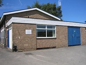
Only one TXE1 was built and this was installed at Leighton BuzzardLeighton Buzzard
-Lower schools:*Beaudesert Lower School - Apennine Way*Clipstone Brook Lower School - Brooklands Drive*Greenleas Lower School - Derwent Road*Dovery Down Lower School - Heath Road*Heathwood Lower School - Heath Road*Leedon Lower School - Highfield Road...
on the site of the former Lake House in Lake Street. This exchange type was developed by three members of the Joint Electronic Research Committee, JERC, which was formed in 1956 and lasted until 1969. This consisted of the British Post Office (GPO
GPO
-Organisations:*General Post Office **General Post Office UK*German Patent Office, *United States Government Printing Office, a federal government agency*Green Party of Ontario, a policial party in Ontario, Canada...
), Siemens Brothers & Co Ltd (shortly to be part of AEI
British Thomson-Houston
British Thomson-Houston was a British engineering and heavy industrial company, based at Rugby, Warwickshire, England. They were known primarily for their electrical systems and steam turbines. They were merged with the similar Metropolitan-Vickers company in 1928, but the two maintained their own...
, who were subsequently merged with GEC in the early 60s), Automatic Telephone & Electric Co. Ltd (known as AT&E and merged with Plessey
Plessey
The Plessey Company plc was a British-based international electronics, defence and telecommunications company. It originated in 1917, growing and diversifying into electronics. It expanded after the second world war by acquisition of companies and formed overseas companies...
in 1961), the British company Ericsson Telephones Ltd (also merged with Plessey in 1961) - see http://web.ukonline.co.uk/freshwater/histatm.htm), General Electric Co. (GEC), and Standard Telephones & Cables Ltd. (STC
Standard Telephones and Cables
Standard Telephones and Cables Ltd was a British telephone, telegraph, radio, telecommunications and related equipment R&D manufacturer. During its history STC invented and developed several groundbreaking new technologies including PCM and optical fibres.The company began life in London as...
). The three members of the JERC who actually built the exchange were STC, AEI and AT&E. STC built the common control, AEI the switching, line scanning and test console, whilst AT&E took care of the dialling capturing equipment (Registers) and the Outgoing Junctions. The actual development of the TXE1 started around 1963, and went into service in 1968. There were models of the AEI equipment at Blackheath, London and of the ATE equipment at Edge Lane, Liverpool. AEI actually called TXE1 their REX (Reed Electronic Exchanges)
Exchange Description
.An equipment practice was needed and it was realised that a matrix of reed relays could be about the same size as a crossbar switch. Therefore the equipment practice of AT&E's crossbar system was adopted for the TXE1 apart from the STC common control who had their own equipment practice. Also, Hivac (then the only UK manufacturer of reed inserts) was an AT&E subsidiary. The STC common control consisted of 14 racks and made up a complete suite of the exchange. It was made entirely from discrete components as Integrated circuit
Integrated circuit
An integrated circuit or monolithic integrated circuit is an electronic circuit manufactured by the patterned diffusion of trace elements into the surface of a thin substrate of semiconductor material...
s were not yet in common use. There was much discussion by all contractors as to whether at the time there was a reliable connector so as to provide the ability to withdraw and replace units. STC decided to have the units withdraw and AT&E did not. It turned out that the connectors were reliable and STC had a great advantage in fault finding. It also allowed the STC engineers to place a suspect faulty unit in an outrigger so it could be tested in situ.
.
.
One of the jobs of the Common Control was to decide which was the best connection to be used through the switching network and this part was called the Route Choice. The Interrogators would return the available paths and the Route Choice would make a choice and tell the Markers to mark that route.
The exchange used reed relay
Reed relay
A reed relay is a type of relay that uses an electromagnet to control one or more reed switches. The contacts are of magnetic material and the electromagnet acts directly on them without requiring an armature to move them...
s as the switching medium, and the reeds themselves were approximately 3 inches in length and the only ones available. TXE2 exchanges would later on use reeds that were half this length. It had multi-stage switching divided into A, B and C switches and there were devices called links to connect the paths together. A typical local call would go ABC Link CBA. There were two types of links: ones with transmission bridges for local calls and others with no bridges for the outgoing junction calls. The bridges for the latter were contained within the outgoing junction units.
.
The exchange had some advanced features at the time, i.e. tone dialling was an option as opposed to pulse dialling, with no post-dialling delay for own exchange calls. It also had the ability to detect a switching failure and go for a repeat attempt without the subscriber being aware of it. Any repeat attempts were printed on a standard teleprinter. It had a futuristic test console, which monitored all the calls on a digital display.
A new approach to the inter rack cabling was taken. A ceiling was built above the top of the racks, creating a cable loft. The cables were just pushed through holes in the cable loft and taken to where they were going by the shortest route. The result was a complete mess of a cable loft, but all cables were labelled; it was quicker and easier than the normal way of lacing all the cables. The exchange was housed in a prototype K type single story building having a special provision reinforced ceiling for the overhead cabling already mentioned. The construction included thermal insulation panels and double-glazing to minimise heat loss and heating was by under floor electrical heaters operated on off-peak supplies. Ventilation arrangements were by eight ventilating units each handling 600 cu. ft. per min and a series of "hit and miss" type louvres above the windows on each side of the building provided outlets for heated air.
.
A novel but subsequently disastrous feature designed by Bell Antwerp was used to hold the subscriber’s Class of Service information i.e. PBX, Shared Service, TOS etc. This was a capacitor store and it held information on a thin plastic strip; into which could be inserted up to 10 little copper squares which had a capacitance of 10 pico farad. The thin plastic strip was then inserted into the Data Store rack at the position representing the directory number. This can be seen in the photograph together with some plastic strips hanging by wire. Hanging the strips by wire was a common practice for subscribers who were constantly changing their Class of Service, i.e. being made TOS. This information was then pulsed by the STC common control Translator and appropriate action taken. STC had enormous trouble getting it to work, which caused a delay to the whole exchange. In the end the problem turned out to be cable interference requiring substantial re-cabling. It was replaced by a threaded-core store called Dimond Rings in TXE3, TXE4 and TXE2, which were extremely reliable.
.
The AT&E Registers looked after all the dialling and there were three sorts of Registers:loop-disconnect
Pulse dialing
Pulse dialing, dial pulse, or loop disconnect dialing, also called rotary or decadic dialling in the United Kingdom , is pulsing in which a direct-current pulse train is produced by interrupting a steady signal according to a fixed or formatted code for each digit and at a standard pulse repetition...
, MF
Multi-frequency
In telephony, multi-frequency signaling is an outdated, in-band signaling technique. Numbers were represented in a two-out-of-five code for transmission from a multi-frequency sender, to be received by a multi-frequency receiver in a distant telephone exchange...
(later called DTMF), and incoming. The local Registers (loop-disconnect and MF) took care of own-exchange and outgoing calls, while the incoming Registers dealt with calls coming into the exchange. A local Register would provide dial tone to the subscriber, wait for the first dialled digit, and then apply to the Translator to see what action was required. The Translator could decide by the first digit if it was a local call and if it was it would instruct the Register to come back when it had all the digits. If it was not a local call and therefore to be routed out of the exchange, then it would tell the Register to come back with each digit until it could decide the routing, as not all calls went to the GSC (Group Switching Centre) as there was AAR (Alternative Available Routing). Once the routing had been decided and digits passed on, the Register was free to take another call.
The MF senders/receivers were used when an MF subscriber initiated a call. They were set up to the subscribers line and switching network to an MF register, they converted the MF tones to pulses for the registers to store. They used the X, Y and auxiliary switching planes.
Incoming Registers used a time-shared electronic dial path (TDM
TDM
TDM is a three-letter acronym that may refer to:In Entertainment may refer to* The Dead Milkmen, punk rock band* Team Deathmatch, multiplayer mode in videogaming...
) to transfer pulsing information from the incoming junction to the Incoming Register. This feature was necessary to ensure that no pulsing information was lost.
The Registers were made entirely from discrete components. The exchange had about 20 Local Registers and 12 Incoming Registers, each Register containing nine double units, which were hinged and could be lowered for easier access. These units unlike the common control were hard wired. However, a unit could be changed by breaking straps at the rear and then rewiring them, but it was a lengthy process taking about an hour to change just one unit on one Register. A subscriber was connected to the Local Register using the normal reed switching as the Local Registers were connected to the C switches. However, they communicated directly to the common control Translator via hard wiring.
The Translator was a complete rack of the common control (in fact rack 12) and its job as the title implies was to translate information and then give the appropriate action to the required part of the exchange.
In the event of a cable breakdown or other similar event which may result in permanent loop
Permanent signal
Permanent Signal in US telephony jargon, or Permanent Loop in British usage, is a condition in which a POTS line is off-hook without connection for an extended period of time. This is indicated in modern switches by the silent termination after the off hook tone times out and the telephone...
s on subscribers lines, after a predetermined time the Register would be forcibly released and the subscriber put into a parked condition. This was possible because each subscriber had a dual armature line relay and in the parked condition the low current armature was operated but the other not. The scanners would ignore any park condition.
The scanners were provided by AEI and as the name implies scanned the subscribers seeking out the ones that had initiated a calling condition. They also detected subscribers in a “parked” condition. The scanners were mounted the racks of the associated switching units and fed back information so that a Register could be switched to the subscriber to provide dial tone.
The exchange was capable of dealing with 10,000 subscribers but it started out with a capacity of 3,000 subscribers, 152 incoming junctions and 166 outgoing junctions and plans were made to double the subscriber capacity this but this never happened. Tracing of calls within the exchange was instantly displayed digitally on the Test Console.
Occasionally the call trace did not work but the engineers worked out a way of manually tracing a call. What they did was to buy a little compass and glue a piece of magnetic ferrite on the side to pull the compass needle away from North. They would then run this compass along outside of the reed relays and when a relay was operated the needle would move back to North. This was repeated over several sets of the switching path until the trace was complete.
AT&E and STC created testers so that parts of the exchange could be taken out of service and the testers connected to these parts. The testers then simulated the signals that the exchange would send to it, and in this way individual parts of the exchange could be tested.
The Out Going (O/G) Junctions were provided by AT&E, and yet again were made of discrete components. There were three O/G junctions per shelf and they could be busied by using the keys that can be seen in the photograph.
There was an interesting opportunity using the three contractors as to how the different parts of the exchange were to be connected together, and much time was spent on this.
A display was created next to the test console, which gave a visual indication of the traffic flowing through the exchange, and it was named the Hubblemeter after the instigator Ray Hubble.
The TXE1 required power supplies of -18 V, +50 V and -50 V DC. These were provided in the usual manner by lead acid rechargeable batteries charged from the 240 Volts AC mains supply and backed up by a diesel generator in case of mains power failure.
The exchange went into service in 1968 and proved reasonably reliable although it did have a few outages. Most of these were caused in the Common Control area. The common control equipment was divided into functional units and each unit was duplicated an A side and a B side and each section was isolated by means of reed relays. Under either fault conditions or manual control or the predetermined time, the unit indicated would change over to its partner. The changeover of the relays was controlled by a series of reed relays whose reed inserts were wetted with mercury. Periodically over some weeks, the mercury would migrate to the point of contact of the blades leaving a mercuric bead giving “ON” and both A and B sides into service. The confusion generated caused the exchange to be isolated.
There were also some problems with the ASY63 transistors that had Nickel Iron connecting wires and would not take the solder causing dry joints to the circuit cards. This happened over all sections of the electronic equipment in the common control area. The remedy to this problem was to re-solder connections with a solder with a stronger flux.
It was withdrawn from service in 1977 when it was replaced by a TXE4. Unfortunately the whole exchange was then scrapped and allegedly the scrap men put a sledgehammer through that lovely console.
TXE1 Floor Plan & Schematic
TXE2
The prototype for the exchange which the GPO called TXE2 was a system called Pentex (the Plessey trademark for all non-GPO sales), which, starting in 1963, was developed by Ericsson Telephones, as part of Plessey. The first field trial of Pentex started in the Peterborough Telephone Area in 1965. There was another trial site at Leamington. The system was designed to serve 200 - 1200 customers and about 240 Erlang units. It was therefore mainly used to replace the larger rural StrowgerStrowger switch
The Strowger switch, also known as Step-by-Step or SXS, is an early electromechanical telephone switching system invented by Almon Brown Strowger...
exchanges - usually UAX13s. The first TXE2 was installed at Ambergate
Ambergate
Ambergate is a village in Derbyshire, England, where the River Amber joins the River Derwent.Until the early nineteenth century it was known as Toadmoor, with no more than a few artisans' cottages. The southerly half of the village was still shown as such on the Ordnance Survey's maps.It is about ...
near Matlock in Derbyshire and it opened on the 15th December 1966. Ambergate was chosen because it was a suitable small exchange (200 lines) which was some 20 miles from the Plessey factory at Beeston, Nottingham. The manual exchange which it replaced was kept on standby for several months, until sufficient operational confidence was developed in the TXE2. Although the system had been developed by Plessey, for security (and perhaps in an attempt to drive prices down) the GPO had insisted on competitive tendering for the TXE2 exchanges. Production contracts were awarded simultaneously to Plessey, STC and GEC, and the distribution of the three manufacturers products into the field was done on an apparently random basis. Some 2-3000 TXE2s went into service with the GPO, the last one being withdrawn from service on June 23 1995.
The Pentex system, which evolved beyond TXE2, was exported to over 30 countries and was largely responsible for Plessey winning the Queen's Award for Exports in 1978.
There is a working TXE2 at Avoncroft Museum. It can be used to make calls within the museum. For a virtual tour inside this Plessey mobile TXE2 (or MXE2, as they were called) at Avoncroft Museum see http://www.connected-earth.com/Daysout/AvoncroftMuseumofHistoricBuildings/Virtualtour/pano009.htm
A few details about the MXE2s are given at http://www.thg.org.uk/mndx/index.htm.
Many of the MXE2s ended up in Northern Ireland. Only one of these ever had to be used 'in anger'. This was at Castlewellan about 1990, when the exchange was blown up by terrorists. The typical set-up time for an MXE2 was about 6 weeks, but at Castlewellan full telephone service was restored using an MXE2 (and the additional use of a mobile transmission unit designed by Northern Ireland staff) within one week of the bombing. It did however take a lot of subsequent work by the switch maintenance Technical Officers to get the exchange up to an acceptable standard of service, as it had been standing idle for several years.
The photograph on the left shows several racks inside Ambergate Exchange. Although the first TXE2-type exchange to go into public service, it actually consisted of Plessy pre-production equipment, called Pentex. The clumsy large handles on the front of the slide-in units are the obvious distinguishing feature. It is also apparent that the racks and units are painted in battleship grey. The change from this to the 'light straw' colour of all subsequent exchanges (including all other TXE2s) was a significant change in an organisation where exchange equipment had been battleship grey for as long as any telephone engineer could remember.
Exchange Description
Because of their common controlCommon control
In telecommunication, a common control is an automatic telephone exchange arrangement in which the control equipment necessary for the establishment of connections is shared by being associated with a given call only during the period required to accomplish the control function for the given call...
design, isolation (inability of the exchange to set up calls) of the entire exchange was always a possibility and very occasionally happened. This potential weakness had been at least partially recognised in the design of the exchange type, so the most critical common control units were split into three sections and each section was duplicated into an A-side and a B-side. In the event of the equipment detecting a serious fault in one of the side-conscious units, all the units in that section were locked onto the side which was giving good service and a prompt alarm was sent to a manned centre to indicate that the exchange needed urgent attention.
In normal service the exchange automatically changed all three sections from one side to the other every 8 minutes. If Call Control detected 8 failures to set up calls within that 8 minutes, then it force-changed all the side-conscious units onto the other side, locked that side in service and raised a prompt alarm. In periods of very low traffic, there would typically be fewer than 8 call set-up attempts on the exchange in 8 minutes and this would have prevented the above security system from working. The exchange was therefore provided with an automatic Test Call Unit, which originated a test call every 30 seconds. As well as thus enabling Call Control to detect 8 failures in less than 8 minutes (if all call-attempts were failing), the Test Call would raise its own prompt alarm if it detected 31 sequential call-attempt failures, indicating that neither security side of the exchange was able to connect calls.
The photograph below right shows the Alarm Indicating Panel at the only remaining working TXE2, at Avoncroft Museum. The red lamps show that all three sections are alarmed. The 8-minute changeover will therefore have been suspended and the white lamps show that all three security sections are locked on to side B. If a maintenance man was called to an exchange because of an extended prompt alarm, this panel would generally be his first port of call in order to see what equipment was in an alarmed state.
As a further security measure, if the first attempt to set-up a path to a Register failed, so that, on an outgoing call, the customer did not get dial-tone, the exchange recognised the failure, stored the details of the equipment in use on the failed call and automatically made a second attempt, using different equipment. This happened so quickly (about 50 milliseconds) that, if the second attempt was successful, the customer would not have been aware of the failed first attempt to get dial-tone.
A security weakness on the rural Strowger exchanges (UAX 13s and smaller) had been the electrical power supply. If the main feed went down, the exchanges relied on back-up batteries, but these could only keep the exchange going for a few hours and after that, service was lost across the whole exchange to typically several hundred customers. The TXE2s were much better equipped. They had a separate power room, itself often bigger than the entire UAX 13, in which, as well as back-up batteries, there was a stand-by diesel generator. This started automatically in the event of a power cut and could keep the exchange going for days. Isolations due to power cuts therefore became a thing of the past, but at considerable initial capital cost.
The picture above of the TXE2 equipment in Hullbridge
Hullbridge
Hullbridge is a village and civil parish in the Rochford district of Essex in east England. Bordered to the north by the River Crouch, and semi-isolated from the nearby towns of Hockley and Rayleigh, Hullbridge has a population of around 7,300 ....
Telephone Exchange gives a good impression of the inside of a typical early TXE2. They were quite spacious (very spacious compared with the Strowger
Strowger switch
The Strowger switch, also known as Step-by-Step or SXS, is an early electromechanical telephone switching system invented by Almon Brown Strowger...
UAX13 which most of them replaced) and with the cleaner generally living locally and taking a pride in the job, they were usually kept very clean and tidy, as in this example. The picture shows the Control Suite in a Plessey exchange. There would typically have been 5 or 6 suites, with plenty more floor space, to allow for growth.
All the TXE2-specific equipment was mounted on slide-in units, mainly single-width, but some double-width. There was a carefully structured holding of maintenance spare units. For those which were likely to be needed frequently or urgently in every exchange, such as a Subscribers Line Unit (a single unit containing the line relays and A-switches for 5 customers), a spare unit was held in every exchange. For those units for which a spare was likely to be needed less frequently or urgently, the spares were held at an Area centre serving perhaps 6-10 TXE2s of the same manufacture. Finally for those units for which a spare was likely to be needed seldom, the spare units were held Regionally. There were 10 Regions in BT at that time.
In TXE2s a call which terminated within the same exchange went through 7 switching stages, whereas a call going out to another exchange went through just 3 switching stages. The switches were designated as A, B, C and D (the paths were ABC for outgoing, ABCDCBA for internal and DCBA for incoming). The common control equipment consisted of B- and C-Switch Selectors, Supervisory Selectors (a Supervisory relay set stayed in-circuit throughout each call), Register Selectors, Registers and Call Control.
The most characteristic feature of the exchange's central control unit design was its mode of operation, a processing of all calls on a one-call-at-a-time basis. This meant that call set-up had to be accomplished in a very short period of time. In particular Call Control had to become free in less than the time of the inter-digital pause on calls incoming to the exchange. This time could be as low as 60 milliseconds. As the TXE2 call-set-up time was some 50 milliseconds, this design requirement was just met, but even so the overall capacity of the system was determined by the probability of an incoming call being delayed too long in its initial connection to a register.
The grade of service
Grade of service
In telecommunication engineering, and in particular teletraffic engineering, the quality of voice service is specified by two measures: the grade of service and the quality of service ....
in a TXE2 was dependent on the number of customers in an A-switch group, with access to just 25 A-B trunks. The normal standard on the earlier exchanges was 125 customers per A-switch group. If the A-switch group contained many busy PBX lines, then the number of customers might be reduced to 75. The earlier (Mark I and Mark II - the differences being slight) exchanges could handle up to 2000 customers. Later on Mark III TXE2s were able to handle up to 4000 customers and on these exchanges, where the average calling rate was sufficiently low, up to 250 customers would be in an A-switch group, still with access to just 25 A-B trunks.
The choice of the main type of memory used in the TXE2 (and the TXE4) was particularly characteristic of the general design philosophy, that the components used had to be of a technology that had been tested over many years. The choice thus went to the 'Dimond ring' type of memory, named after T.L.Dimond of Bell Laboratories, who invented them in 1945. They were large-diameter magnetic ferrite toroidal rings with solenoid windings, through which are threaded writing and reading wires. This set-up is shown fairly clearly in the picture (above) of the Ambergate Calling Number Generator and Class of Service racks. These racks gave the ability to convert a subscriber's directory number into an equipment location identity. This was a considerable innovation in British exchanges, since in Strowger exchanges the directory and equipment numbers had to be the same.
Reed relay
A reed relay is a type of relay that uses an electromagnet to control one or more reed switches. The contacts are of magnetic material and the electromagnet acts directly on them without requiring an armature to move them...
s and a typical TXE2 contained about 100,000 reeds. A 'reed' was actually two over-lapping ferromagnetic blades hermetically sealed within an inert-gas-filled glass capsule. The blades were gold-plated and separated by just a few thousandths of an inch. The reeds were fast in operation (about 1 millisecond), with a life expectancy of more than 10 million operations. The glass capsules were about an inch (25 mm) in length and about an eighth of an inch (3 mm) in diameter. Four reeds were generally present inside each relay coil, two for the speech-path, one for holding the path and one for metering. Switching with these reeds held out the prospect of much greater reliability compared with the Strowger system, where switching was carried out by base metal wipers moving through banks of metal contacts. The Strowger switches required routines to be carried out on them to clean the banks: they also required oiling and occasional adjustment. Reed relays required none of this. However, in practice, and particularly in the early years of the system's service, the performance of the reeds proved to be less good than had been expected.
The picture (right) of a TXE2 Supervisory relay-set gives an idea of the technology involved. Designed in the 1960s, it consisted of discrete components mounted on circuit boards. These relay sets were of double width. On the face-plates there were two built-in lamps (for call-tracing and fault indication) and a block of test points, which gave test access to the circuits inside. Three "candles" can be seen protruding from units: these were simple indicator-bulbs which were used as required to show when the relay sets were in use. These "candles" or "busy indicators" were used throughout the exchange as part of fault-finding.
The TXE2-specific equipment was different in the TXE2s manufactured by Plessey, STC and GEC, so that spare equipment had to be held for each type of manufacturer. Importantly, each manufacturer made their own reed inserts (GEC's were actually made by one of their subsidiary companies, the Mazda Osram Valve Company) and their performance differed significantly in the first years of production.
Edge connector
An edge connector is the portion of a printed circuit board consisting of traces leading to the edge of the board that are intended to plug into a matching socket. The edge connector is a money-saving device because it only requires a single discrete female connector , and they also tend to be...
. It was feared that this type of connector would cause problems after a relatively low number of removal/re-insertion operations, but in practice they proved to be more than adequately robust.
The STC reeds proved to be more reliable, but, if they failed, they tended to stick or fail short-circuit. This was also a cause of isolations early on, but a simple modification restricted the most serious failure to a small part of the exchange. The GEC/MOV reeds proved to be the most reliable of all.
Once the teething troubles had been largely dealt with, which was not until about 1974, the TXE2s realised more of their expected benefits and it was eventually not uncommon for one Technical Officer to maintain the operation of three of these exchanges, serving perhaps some 5-6000 customers in total.
TXE3
TXE3 was a cost reduced and improved version of TXE1 designed for exchanges with more than 2000 subscribers and was very similar in design to the later TXE4. The same three companies that built the TXE1 developed TXE3, namely STC, AEI and AT&E and it was intended to be the standard BPO system for large exchanges. The prototype exchange was built and tested in the Circuit Laboratory at Armour House. The trial period was for 200 subs, 100 were for senior engineers within Telecoms HQ the remaining 100 subs were transferred from Monarch exchange, in the City of London, on a temporary basis (via c/o switches in case something went wrong). The trial lasted from 1969 until 1970.During the development of the TXE3 it became apparent that the system would be too expensive for the competitive export market, so AEI split its team into two: one to do whatever the BPO wanted and the other to produce a reduced version for export. The trial was started in April 1968 and the model worked very well at Armour House and the BPO ordered the first half dozen exchanges. Jim Warman moved his team back from Blackheath to Woolwich to start a new department with its own manufacturing and marketing. The equipment for the first exchange had been manufactured with a 9600 capacity and was being installed on site at Royal exchange in London in 1968 when GEC made a takeover bid for AEI who were in financial difficulties brought about by the development costs of TXE1 and TXE3. The takeover bid was and GEC decided, unbelievably, that they preferred the crossbar system to TXE3 and promptly cancelled the contract to supply TXE3 to the BPO. Royal first exchange was dismantled before its installation had been completed and all the TXE3 equipment was broken up and supplied to universities for observation.
Exchange Description
The TXE 3 exchange consists of three main areas:—(1) Peripheral equipment comprising subscribers' line circuits, junction terminations and other units providing a variety of special functions such as coin and fee checking on coin box calls.
(2) A switching area through which connections are established between peripheral equipment. It is arranged to give three stages of switching on either side of centrally located link circuits
(3) A control area, that received information from peripheral equipment and the switching area, and processed this with data held in its own store to determine the actions required. It issued instructions to the other areas and checks their successful completion, making second attempts if necessary.
The control area was called the Main Control Unit(MCU) and there were two provided on the model for security although a maximum of 12 could have been provided. Each MCU was capable of handling approximately 6,000 instructions per hour. The MCU operated in accordance with an instruction program stored in the form of a number of wires threading a bank of magnetic cores. Changes in the operating sequence can be obtained by program changes involving the re-threading of a number of wires in the store instead of by widespread re-wiring within and between a multitude of separate units.
Line scanning circuits sequentially examined the state of each line, junctions and so on by means of a pulse many times a second and immediately after each pulse a data store (the Cyclic Store) offered the MCU permanent information relating to the line. When a calling condition was detected, the scanning pulse was passed to the MCU indicating to it that a new call had to be set up and busying it temporarily to further calls. As the first steps in dealing with the new call the MCU recorded the directory number and class of service (shared service, PABX line, incoming junction register, TOS and so on) information offered by the Cyclic Store and allocates one of its associated group of up to 30 registers. The registers were connected to peripheral terminals of the switching network, in the same way as subscribers' lines, junction circuits and other units and the MCU proceeded to issue instructions to the network to connect the subscriber and register terminals.
The switching network was composed of reed relay cross-points arranged to give three (A, B and C) stages of switching on either side of a number of linking circuits. The A-stage switches concentrate traffic from the peripheral terminals on to B-C-stage arrays, which are internally connected to provide full accessibility between every B-switch terminal and every C-switch terminal of the array. A simple switch enabling two subscribers to be connected to two others can be constructed, but extending this to larger sizes becomes increasingly uneconomic. Nevertheless, by splitting the network into two stages, considerable economy could be affected.
To connect the allotted registers to the calling line, the MCU asked the interrogator-markers to identify all free paths from the subscriber to the central, "through" type, links and from the register to the links. This information was returned to the Route Choice Unit, which then identified those link circuits, which were available to both peripheral terminals, and selected the most suitable, according to predetermined rules chosen to make maximum use of the network. Its decision was signalled back to the MCU which then instructed the interrogator-markers to mark the chosen pair of paths, starting from the link out through the C, B and A stages to the subscriber, and then from the other side of the same link, through C, B and A-stages to the register.
The subscriber dialled the required number and as each digit was received it was stored in electronic circuits within the register, which will call for the MCU after each digit and ask for instructions. Until sufficient digits have been received to determine the outgoing route from the exchange, the instruction will be "apply again after the next digit" and the MCU returned to serving other demands.
When sufficient digits had been received, the MCU would have been able to determine the required path through the exchange, the routing digits to be sent (if an outgoing call is indicated), and which of the received digits have to be repeated forward. It would advise the register accordingly and then set the paths necessary to allow the register to signal forward and finally extend the caller to the required number or junction.
On calls which terminated on the exchange a transmission bridge and supervisory circuit needed to be introduced within the switching network. This was done by employing a "bridge link" in the final connection. To allow metering on own-exchange calls these links also contain local call timing elements which pulse the P-wire in the desired "X" or "Y" phase at the appropriate times. "X" and "Y" phases were only required to support the metering for shared service subscribers, which has long since disappeared thankfully.
Similar procedures would be followed for any other type of call. In every case the MCU would decide, in accordance with its program instructions, what connection pattern was appropriate in the circumstances indicated and issue orders for setting the paths.
Within each MCU information was handled in a "two-out-of-five" code which enabled errors to be detected, and the output of the program store was duplicated to give additional protection.
The TXE 3 model gave satisfactory service and the experience gained from the model confirmed the validity of the basic design and led to the development of the TXE4.
Continued Development
There now was a hiatus before the development of TXE4 started. GEC made a takeover bid for AEI and this was accepted by the majority of shareholders. As a result of this TXE3 was "killed off" in favour of crossbar a decision that severely hindered the TXE program. The BPO found that it had gone from obsolete Strowger to obsolete Crossbar. It was after this that the BPO asked STC to develop TXE3 into TXE4 that the TXE program was resumed. There was a gap therefore of about 3-4 years in the TXE development and much of the expertise was lost, in fact none of the TXE3 team worked on TXE4, and it is a credit to STC that they managed to get TXE4 into service as quickly as they did.TXE4
STC
- Education :* S. Thomas' College, Mt Lavinia, a private school in Sri Lanka* South Texas College* South Thames College* Sha Tin College, Hong Kong* Saint Theresa's College, Philippines- Organizations :* Scarborough Town Centre* Space Transport Corporation...
to a specification from the GPO. It was built at the STC Southgate factory in north London and used reed relays as the switching medium which proved reliable in service. Later a small amount of exchanges were also manufactured by PLessy and GEC. It had a programmable common control called the Main Control Unit (MCU) and each exchange had at least three MCUs for security and a maximum of twenty, but in theory could operate with just one. It had a unit called the Supervisory Control Unit, which took control of the calls from information supplied to it by the MCU.
The man responsible for marketing strategy of STC at the time, Ken Frost said “We took a chance on going into TXE4. In the first place without any firm commitment from the Post Office. And then we got into the great modernisation programme, in which we argued for modernisation with TXE4 while Plessey and GEC made their case for crossbar with some electronic control on it. The Post Office decision was for TXE4”.
To prove the enhancements of TXE4 over the TXE3 a test bed trial installation was installed in Tudor exchange in North London in 1969. After a successful two year trial a contract was placed with STC for the provision of £15million of TXE4 equipment in June 1971.
The first actual production TXE4 was installed in 1973 at Rectory, a suburb of Birmingham brought into service on the 28th February 1976. TXE4 is sometimes is known as TXE4RD where the RD stood for Rectory Design. Rectory opened with 4300 subscribers and had a maximum capacity of 8000. In 1983 there were 350 TXE4s in service serving 4 million customers. The last TXE4s were taken out of service (at Selby, Yorkshire and Leigh-on-Sea, Essex) on March 11 1998.
Exchange Description
The switching was via reed relays and multi stage like the TXE1. The difference from the TXE1 design was that an extra switching stage called the D switch was added. Thus, a typical path would be ABC Link DCBA. There was much debate about the D switch and whether it was necessary and it was an idea that Jim Warman had worked hard to avoid, nevertheless it was used to simplify growth problems.Subscriber information was programmed into the exchange in racks called cyclic stores which used PTFE wire threaded through magnetic cores known as 'Dimond ring'(see TXE2 section for more information). The information stored was the Class of Service (COS) i.e. PBX, CCB (payphone
Payphone
A payphone or pay phone is a public telephone, often located in a phone booth or a privacy hood, with pre-payment by inserting money , a credit or debit card, or a telephone card....
) or single line, followed by the directory number. The subscribers derived an equipment number from the position on the cyclic store rack. This was a six-digit number and referred to as the MUCKBL, which describes to the exchange where this is. In some parts of the exchange equipment the equipment number was used as BUMCLK and this was used by engineers as a pseudo swear word. When a subscriber lifted their handset it sent a pulse down this wire, which was picked up by a 156 msec scanner, which initiated a path to be set up through the reed relays so the subscriber could be connected to a Register. This Register then returned dialling tone to the subscriber and dialling could commence.
The Registers were "owned" by the MCUs and each MCU had a maximum of 36 Registers. The MCU was responsible for looking after all of its Registers and deciding from the dialled information where the call was going to be routed. Once it decided this, it sent a command to the Interrogator/Markers to set up the required path and then moved on to the next task. Once the connection had been established, the SPU took care of the path and all the call metering tasks. The MCUs all had 36 Registers and had solid-state memory to hold the dialled digits from all the Registers and also had other storage to manipulate call set-up information.
There were three scan rates: 156ms for subscribers, 36ms for Registers and Outgoing Junctions, and 12ms for Incoming Junctions. The last of these was the quickest scan, to ensure that no pulses were lost from the incoming junctions.
As the exchange ran on timing pulses, unlike the TXE2 design, there was a Pulse Generator Rack, which provided them. The generator used a delay line oscillator of 166.7 kHz to produce a basic pulse of 6 microsecond’s duration and this was fed to 8 ring counters which then multiplied up the basic 6 microsecond pulses into the various pulse requirements. There were four generators, because of security reasons, and of the vital importance of these pulses. The exchange could still function if one generator was out of service.
A problem was discovered very late in the development of the TXE4 in that an equipment number could be threaded with the wrong directory number by mistake. Even worse it could be the directory number of another equipment number leading to multiple directory numbers. The exchange had no way of detecting this but the problem was solved in a very novel way.
The 5000 programming steps were named with the letters A-E and then three numbers e.g. B525. Each step consisted of 8 pieces of information and these were of value from 1 to 10 depending on what core the wire was threaded through. The first three digits told the MCU what program step to go to next e.g. 891 and the first letter being decided usually by a decision i.e. whether some information was present A=yes, B=no resulting in either A891 or B891. The next two pieces of information gave what the operation was e.g. 55 compare two pieces of information and the last three told the MCU where to store the result i.e. 020 put this information in MFS (Main Ferrite Store) 10(see next paragraph for more information). So the whole programme step would be 89155020. Each step took 12 microseconds to execute. This program, the software of the exchange, could easily be changed as developments and upgrades occurred throughout the life of the TXE4 design.
The MCU contained a non-volatile data store, which used core store. There were three types of data store, Main Ferrite Store (MFS), Special Ferrite Store (SFS) and Register Ferrite Store (RFS). The MFS was used by the MCU itself to hold data for various reasons and the SFS was used for manipulating data. An example of this was that SFS2 could take the data stored is positions 1-5 and swap them with data stored in positions 6-10. It can be seen from this that each store had 10 positions and each one could hold values from 1 to 10. Incidentally this was stored in 2 out of 5 code
Two-out-of-five code
In telecommunication, a two-out-of-five code is an m of n code that provides exactly ten possible combinations, and thus is popular for representing decimal digits using five bits...
. I.e. 11000 = 1, 10100=2, 01100=3. The RFS held data from each of the MCU’s associated registers e.g. dialled digits. There were 20 MFS, 4 SFS and up to 36 RFS.
The MCU was in control of setting up switching paths and it knew when a path had not been successful. In this case the MCU would instigate a repeat attempt to set a new path. The details of the failed path were sent to the printer.
The TXE4 had two standard Teleprinter
Teleprinter
A teleprinter is a electromechanical typewriter that can be used to communicate typed messages from point to point and point to multipoint over a variety of communication channels that range from a simple electrical connection, such as a pair of wires, to the use of radio and microwave as the...
, which were used to give fault indications and other information. The difficulty of manually spotting trends brought an attempt to take the paper tape that the tele-printer produced, as well as the print, and automatically analyse it. It was called PATE4, which stood for Print Analysis TXE4 and was a software programme that read the paper tape looking for common fault patterns.
The TXE4 exchanges were designed for a Mean Time Between Failures (MTBF) of 50 years and, although this was never quite achieved, it could be argued that the design requirement had been met if you discounted human interventions!
Incomplete List of TXE4 Exchanges
| Exchange Name | Region | Opening Date | Closing Date | Exchange Name | Region | Opening Date | Closing Date | |
|---|---|---|---|---|---|---|---|---|
| Ashton on Ribble | NE | NA | NA | Haverhill | Eastern | 25/08/1981 | NA | |
| Atherton | NE | NA | NA | Headington | Eastern | 19/11/1980 | NA | |
| Basingstoke | NA | NA | NA | Henley | Northern HC | NA | NA | |
| Belstead | Eastern | 11/05/1982 | NA | Horsham Carfax | SE | NA | NA | |
| Blackburn | NW | NA | NA | Kettering | Midland | 19/11/1980 | NA | |
| Blackpool | NW | NA | NA | Langley South | Northern HC | NA | NA | |
| Bolton | NW | NA | NA | Leagrave | Eastern | 02/09/1981 | NA | |
| Bowes Park(London) | London | NA | NA | Leeds Headrow | NE | NA | NA | |
| Bracknell | Northern HC | NA | NA | Leighton Buzzard | Eastern | 00/00/1997 | NA | |
| Bradwell Abbey (Milton Keynes) | Eastern | 28/08/1979 | NA | Letchworth | Eastern | NA | NA | |
| Cambridge Central | Eastern | 31/07/1979 | NA | Liverpool | NW | NA | NA | |
| Canvey Island | Eastern | NA | NA | |Maghull | NW | NA | NA | |
| Catford | London | NA | NA | Middlesbrough | NE | NA | NA | |
| Caversham Reading | Northern HC | NA | NA | Muswell Hill | London | NA | NA | |
| Cherry Hinton (Cambridge) | Eastern | 04/08/1981 | NA | Newmarket | Eastern | 18/08/1982 | NA | |
| Chesham | Eastern | 28/05/1981 | NA | Norwich | Eastern | 16/02/1985 | NA | |
| Clacton | Eastern | 25/05/1982 | NA | Nottingham Crusader | NA | NA | NA | |
| Cosham | SE | NA | NA | Oxford City | Eastern | NA | NA | |
| Crowthorne | Northern HC | NA | NA | Port Talbot | WM | NA | NA | |
| Dorchester | SE | NA | NA | Reading South | Northern HC | NA | NA | |
| Fareham | SE | NA | NA | Rectory | Midland | 28/02/1976 | NA | |
| Felixstowe | Eastern | 05/03/1983 | NA | Selby | NE | NA | 11/03/1998 | |
| Fleet | Northern HC | NA | NA | Scarborough | NE | NA | NA | |
| Gerrards Cross | Northern HC | NA | NA | Sheppards Bush | London | NA | NA | |
| Gorleston | Eastern | 26/01/1983 | NA | Southend | Eastern | NA | NA | |
| Great Yarmouth | Eastern | NA | NA | Stevenage | Eastern | 12/07/1983 | |NA | |
| Guildford | Northern HC | NA | NA | Watford | London | NA | NA | |
| Harwich | Eastern | 29/06/1984 | NA | Wolverhamton | Midland | NA | NA | |
| Havant | SE | NA | NA | Woolston | SE | NA | NA |
TXE4A
TXE4A was the last in the line of TXE exchanges and an improved version of the TXE4 design. This was again developed by STC after BT commissioned them, in 1975, to produce a 15% reduction in cost and provide more customer facilities. It had the same switching as TXE4 but an upgraded common control, using integrated circuits (including some of the first microprocessors) to achieve significant size and cost reductions.TXE4A dispensed with Dimond rings and used solid state memory. This allowed for changes to exchange data i.e. customer information to be made by keyboard instead of by laboriously threading jumpers through Dimond rings.
The first TXE4A to enter service was Belgrave, Leicester on 28 February 1981. Altogether over 550 TXE4 and TXE4A exchanges were installed and they were around for over 20 years serving 8 million lines. During its life the TXE4/A system proved to be highly successful and reliable until eventually replaced by System X. The TXE4 era came to an end on the 11th March 1998 when Selby and Leigh-on-Sea were replaced by digital exchanges.
Incomplete List of TXE4A Exchanges
| Exchange Name | Region | Opening Date | Closing Date | Exchange Name | Region | Opening Date | Closing Date | |
|---|---|---|---|---|---|---|---|---|
| Belgrave | Midland | 20/02/1981 | NA | Hampden Park | NA | NA | NA | |
| Ascott | Northern HC | NA | NA | Hayling Island | SE | NA | NA | |
| Bicester | Eastern | NA | NA | Horley | SE | NA | NA | |
| Bognor Regis | SE | NA | NA | Isle of Man | NW | NA | NA | |
| Chelmsford | Eastern | NA | NA | Leigh-on-Sea | Eastern | NA | 11/03/1998 | |
| Clevedon | Wales&West | NA | NA | Queensmere Slough | Northern HC | NA | NA | |
| Colchester | Eastern | NA | NA | Shoreham-By-Sea | SE | NA | NA | |
| Colchester (High Woods) | Eastern | NA | NA | Stanford le Hope | Eastern | 28/11/1982 | NA | |
| Dunstable | Eastern | NA | NA | Stevenage | Eastern | NA | NA | |
| Eastbourne Neville | SE | NA | NA | Summertown | Eastern | NA | NA | |
| Eastwood (Southend) | Eastern | NA | NA | Tilehurst Reading | Northern HC | NA | NA | |
| Fleet | Northern HC | NA | NA | Waterlooville | SE | NA | NA | |
| Grays Thurrock | Eastern | NA | NA | Windsor | Northern HC | NA | NA |
TXE4E
TXE4E was developed and introduced in the late 1980s to update the TXE4 and to add some of the advantages of TXE4A.Exchange Description
TXE4E basically replaced the ten Minature Threaded Wire Stores (MTWS) in the MCU with just two, each containing six re-programmable chips which could be removed and updated with changes via a separate computer. The Cyclic Stores threading fields (12mS x 156mS & 3 x 36mS) were commoned and all new subscribers, ceases or change of Class Of Service, which were threaded previously, were now done via a terminal. This brought it more in line with TXE4A. The other big update of the TXE4E system was the provision of Common Channel Signalling (C7) for all the junction routes. This was controlled from the enhancement racks and updated via the system's onboard terminal and screen.The system also had the capability to busy equipment and reset alarms remotely.
The cyclic store gates, where all the subscriber information was held, were replaced by solid state devices as phase 2 of the enhancement.
TXE5
TXE5 is believed to have been reserved for an improved version of the TXE2. Such a version was never produced.TXE6
Strowger switch
The Strowger switch, also known as Step-by-Step or SXS, is an early electromechanical telephone switching system invented by Almon Brown Strowger...
exchanges, and known as the Electronic Reed Selector System or Reed Group Selector(RGS). Only two were built: one in London and the other at Leighton Buzzard
Leighton Buzzard
-Lower schools:*Beaudesert Lower School - Apennine Way*Clipstone Brook Lower School - Brooklands Drive*Greenleas Lower School - Derwent Road*Dovery Down Lower School - Heath Road*Heathwood Lower School - Heath Road*Leedon Lower School - Highfield Road...
. The one in London was moved and combined with the one at Leighton Buzzard, incidentally the Leighton Buzzard one was coloured light straw and the London one grey so when they were combined it was easy to tell where each unit came from.
Exchange Description
The TXE6 consisted, basically, of two parts; a unit for receiving digits at 10 pulses per second (p.p.s.), followed by a two-stage cross-point-switch. The 10 p.p.s. unit was the interface, converting information from dialled pulses, in Strowger form, to fast parallel signal conditions for the reed group-selector registers. The 10 p.p.s. unit was equipped with four controls and on each there are 96 access-circuits making a total input of 384 junctions. The intermediate switching-unit also had four controls each of which was divided into two parts. Each part controlled a switching unit of 48 inlets and 200 outlets arranged over 10 levels. This gave a total of 1,600 outlets over the ten levels or 160 trunks per level. The outlets were graded over the four controls. A feature of the TXE6 unit was that two equipment levels could be combined to give an availability of 40 trunks from any one level. This facility was used at Leighton Buzzard. The TXE6 went into service on the night of the 18th August 1971 and proved very reliable until withdrawn from service in 1977.Time Line of TXE Exchanges
| Date | Action |
|---|---|
| 1956 | JERC formed |
| 1959 | Prototype TDM Time-division multiplexing Time-division multiplexing is a type of digital multiplexing in which two or more bit streams or signals are transferred apparently simultaneously as sub-channels in one communication channel, but are physically taking turns on the channel. The time domain is divided into several recurrent... Model Exchange Dollis Hill |
| 1962 | Highgate Wood Telephone Exchange Highgate Wood Telephone Exchange The Highgate Wood Telephone Exchange was a telephone exchange built in the London suburb of Highgate Wood. It was the site of a trial for an electronic telephone exchange built by members from Joint Electronic Research Council , which was formed in 1956 and consisted of the British Post Office GPO,... |
| 1963 | JERC agrees to return TDM to research and concentrate development on Reed Systems |
| TXE1 development started | |
| Plessey started development of TXE2 | |
| 1964 | TXE3 design initiated |
| 1965 | TXE2 Field Trial started at Peterborough |
| 1966 | First TXE2 in service at Ambergate |
| 1968 | First and only TXE1 opens at Leighton Buzzard |
| TXE3 trial started, then abandoned by GEC for commercial reasons. | |
| 1969 | JERC ended |
| 1971 | Contract placed with STC for TXE4 |
| TXE6 enters service | |
| 1976 | First TXE4 opens at Rectory, a suburb of Birmingham |
| 1977 | TXE6 withdrawn from service |
| TXE1 withdrawn from service | |
| 1981 | First TXE4A opens |
| 1995 | Last TXE2 removed from service |
| 1998 | Last TXE4 removed from service |
| Last TXE4A removed from service |