
Space Shuttle main engine
Overview
Pratt & Whitney Rocketdyne
Pratt & Whitney Rocketdyne is a United States company that designs and produces rocket engines that use liquid propellants. Pratt & Whitney Rocketdyne, headquartered in Canoga Park, California, is a division of Pratt & Whitney, itself a wholly owned subsidiary of United Technologies Corporation...
for the Space Shuttle
Space Shuttle
The Space Shuttle was a manned orbital rocket and spacecraft system operated by NASA on 135 missions from 1981 to 2011. The system combined rocket launch, orbital spacecraft, and re-entry spaceplane with modular add-ons...
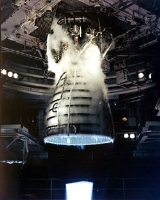
, running on liquid hydrogen and oxygen. Each Space Shuttle was propelled by three SSMEs mated to one powerhead. After each flight, the three SSMEs were removed from the Space Shuttle orbiter
Space Shuttle Orbiter
The Space Shuttle orbiter was the orbital spacecraft of the Space Shuttle program operated by NASA, the space agency of the United States. The orbiter was a reusable winged "space-plane", a mixture of rockets, spacecraft, and aircraft...
, inspected and refurbished in preparation for reuse on a subsequent flight. A total of 46 reusable SSME engines were flown as part of the STS program.
The Space Shuttle main engines burned liquid hydrogen
Liquid hydrogen
Liquid hydrogen is the liquid state of the element hydrogen. Hydrogen is found naturally in the molecular H2 form.To exist as a liquid, H2 must be pressurized above and cooled below hydrogen's Critical point. However, for hydrogen to be in a full liquid state without boiling off, it needs to be...
and liquid oxygen
Liquid oxygen
Liquid oxygen — abbreviated LOx, LOX or Lox in the aerospace, submarine and gas industries — is one of the physical forms of elemental oxygen.-Physical properties:...
from the Space Shuttle external tank
Space Shuttle external tank
A Space Shuttle External Tank is the component of the Space Shuttle launch vehicle that contains the liquid hydrogen fuel and liquid oxygen oxidizer. During lift-off and ascent it supplies the fuel and oxidizer under pressure to the three Space Shuttle Main Engines in the orbiter...
.