

Schmitt trigger
Encyclopedia
In electronics
, Schmitt trigger is a generic name of threshold circuits with positive feedback having a loop gain
> 1. The circuit is named "trigger" because the output retains its value until the input changes sufficiently to trigger a change: in the non-inverting configuration, when the input is higher than a certain chosen threshold, the output is high; when the input is below a different (lower) chosen threshold, the output is low; when the input is between the two, the output retains its value. This dual threshold action is called hysteresis
and implies that the Schmitt trigger possess memory
and can act as a bistable circuit (latch
). There is a close relation between the two kinds of circuits: a Schmitt trigger can be converted into a latch and a latch can be converted into a Schmitt trigger.
Schmitt trigger devices are typically used in open-loop controller
configurations for noise immunity and closed loop
negative feedback
configurations to implement bistable regulators, triangle/square wave generators
, etc.

scientist Otto H. Schmitt in 1934 while he was still a graduate student, later described in his doctoral dissertation (1937) as a "thermionic trigger". It was a direct result of Schmitt's study of the neural impulse propagation in squid
nerves.
 Circuits with hysteresis are based on the fundamental positive feedback idea: any active circuit can be made to behave as a Schmitt trigger by applying a positive feedback so that the loop gain
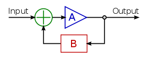
is more than one. The positive feedback is introduced by adding a part of the output voltage to the input voltage; so, these circuits contain an attenuator (the B box in the figure on the right) and a summer (the circle with "+" inside) in addition to an amplifier acting as a comparator. There are three specific techniques for implementing this general idea. The first two of them are dual versions (series and parallel) of the general positive feedback system. In these configurations, the output voltage increases the effective difference input voltage of the comparator by decreasing the threshold or by increasing the circuit input voltage; the threshold and memory properties are incorporated in one element. In the third technique, the threshold and memory properties are separated.
Dynamic threshold (series feedback): when the input voltage crosses the threshold in some direction the very circuit changes its own threshold to the opposite direction. For this purpose, it subtracts a part of its output voltage from the threshold (it is equal to adding voltage to the input voltage). Thus the output affects the threshold and does not impact on the input voltage. These circuits are implemented by a differential amplifier with series positive feedback where the input is connected to the inverting input and the output - to the non-inverting input. In this arrangement, attenuation and summation are separated: a voltage divider acts as an attenuator and the loop acts as a simple series voltage summer. Examples: the classic transistor emitter-coupled Schmitt trigger, op-amp inverting Schmitt trigger, etc.
Modified input voltage (parallel feedback): when the input voltage crosses the threshold in some direction the circuit changes the very input voltage in the same direction (now it adds a part of its output voltage directly to the input voltage). Thus the output "helps" the input voltage and does not affect the threshold. These circuits can be implemented by a single-ended non-inverting amplifier with parallel positive feedback where the input and the output sources are connected through resistors to the input. The two resistors form a weighted parallel summer incorporating both the attenuation and summation. Examples: the less familiar collector-base coupled Schmitt trigger, op-amp non-inverting Schmitt trigger, etc.
Some circuits and elements exhibiting negative resistance
can also act in a similar way: negative impedance converter
s (NIC), neon lamps, tunnel diode
s (e.g., a diode with an "N"-shaped current–voltage characteristic in the first quadrant), etc. In the last case, an oscillating input will cause the diode to move from one rising leg of the "N" to the other and back again as the input crosses the rising and falling switching thresholds.
Two different unidirectional thresholds are assigned in this case to two separate open-loop comparators (without hysteresis) driving an RS trigger (2-input memory cell). The trigger is toggled high when the input voltage crosses down to up the high threshold and low when the input voltage crosses up to down the low threshold. Again, there is a positive feedback but now it is concentrated only in the memory cell. Example: 555 timer, switch debounce circuit.
 The symbol for Schmitt triggers in circuit diagrams is a triangle with a symbol inside representing its ideal hysteresis curve.
 The original Schmitt trigger is based on the dynamic threshold idea that is implemented by a voltage divider with a switchable upper leg (the collector resistors Rc1 and Rc2) and a steady lower leg (RE). T1 acts as a comparator
with a differential input (T1 base-emitter junction) consisting of an inverting (T1 base) and a non-inverting (T1 emitter) inputs. The input voltage is applied to the inverting input; the output voltage of the voltage divider is applied to the non-inverting input thus determining its threshold. The comparator output drives the second common collector
stage T2 (an emitter follower) through the voltage follower R1-R2. The emitter-coupled transistors T1 and T2 actually compose an electronic double throw switch that switches over the upper legs of the voltage divider and changes the threshold in a different (to the input voltage) direction.
This configuration can be considered as a differential amplifier
with series positive feedback between its non-inverting input (T2 base) and output (T1 collector) that forces the transition process. There is also a smaller negative feedback introduced by the emitter resistor RE. To make the positive feedback dominate over the negative one and to obtain a hysteresis, the proportion between the two collector resistors is chosen Rc1 > Rc2. Thus less current flows through and less voltage drop is across RE when T1 is switched on than in the case when T2 is switched on. As a result, the circuit has two different thresholds in regard to ground (V- in the picture).
Initial state. For NPN transistors as shown, imagine the input voltage is below the shared emitter voltage (high threshold for concreteness) so that T1 base-emitter junction is backward-biased and T1 does not conduct. T2 base voltage is determined by the mentioned divider so that T2 is conducting and the trigger output is in the low state. The two resistors Rc2 and RE form another voltage divider that determines the high threshold. Neglecting VBE, the high threshold value is approximately
 .
.
The output voltage is low but well above the ground. It is approximately equal to the high threshold and may not be low enough to be a logical zero for next digital circuits. This may require additional shifting circuit following the trigger circuit.
Crossing up the high threshold. When the input voltage (T1 base voltage) rises slightly above the voltage across the emitter resistor RE (the high threshold), T1 begins conducting. Its collector voltage goes down and T2 begins going cut-off, because the voltage divider now provides lower T2 base voltage. The common emitter voltage follows this change and goes down thus making T1 conduct more. The current begins steering from the right leg of the circuit to the left one. Although T1 is more conducting, it passes less current through RE (since Rc1 > Rc2); the emitter voltage continues dropping and the effective T1 base-emitter voltage continuously increases. This avalanche-like process continues until T1 becomes completely turned on (saturated) and T2 turned off. The trigger is transitioned to the high state and the output (T2 collector) voltage is close to V+. Now, the two resistors Rc1 and RE form a voltage divider that determines the low threshold. Its value is approximately
 .
.
Crossing down the low threshold. With the trigger now in the high state, if the input voltage lowers enough (below the low threshold), T1 begins cutting-off. Its collector current reduces; as a result, the shared emitter voltage lowers slightly and T1 collector voltage rises significantly. R1-R2 voltage divider conveys this change to T2 base voltage and it begins conducting. The voltage across RE rises, further reducing the T1 base-emitter potential in the same avalanche-like manner, and T1 ceases to conduct. T2 becomes completely turned-on (saturated) and the output voltage becomes low again.
 Non-inverting circuit. The classic non-inverting Schmitt trigger can be turned into an inverting trigger by taking Vout from the emitters instead from T2 collector. In this configuration, the output voltage is equal to the dynamic threshold (the shared emitter voltage) and both the output levels stay away from the supply rails. Another disadvantage is that the load changes the thresholds; so, it has to be high enough. The base resistor RB is obligatory to prevent the impact of the input voltage through T1 base-emitter junction on the emitter voltage.
Direct-coupled circuit. To simplify the circuit, the R1–R2 voltage divider can be omitted connecting T1 collector directly to T2 base. The base resistor RB can be omitted as well so that the input voltage source drives directly T1 base. In this case, the common emitter voltage and T1 collector voltage are not suitable for outputs. Only T2 collector should be used as an output since, when the input voltage exceedes the high threshold and T1 saturates, its base-emitter junction is forward biased and transfers the input voltage variations directly to the emitters. As a result, the common emitter voltage and T1 collector voltage follow the input voltage. This situation is typical for over-driven transistor differential amplifiers and ECL gates.
The emitter-coupled Schmitt trigger has not low enough level at output logical zero and needs an additional output shifting circuit. The collector-coupled trigger has extremely low (almost zero) output level at output logical zero.
or the more dedicated comparator
.Usually, negative feedback is used in op-amp circuits. Some operational amplifiers are designed to be used only in negative-feedback configurations that enforce a negligible difference between the inverting and non-inverting inputs. They incorporate input-protection circuitry that prevent the inverting and non-inverting inputs from operating far away from each other. For example, clipper circuit
s made up of two general purpose diode
s with opposite bias in parallel http://www.analog.com/library/analogdialogue/archives/42-10/off_amps.html or two Zener diode
s with opposite bias in series (i.e., a double-anode Zener diode) are sometimes used internally across the two inputs of the operational amplifier. In these cases, the operational amplifiers will fail to function well as comparators. Conversely, comparators are designed under the assumption that the input voltages can differ significantly. An open-loop
op-amp and comparator may be considered as an analog-digital device having analog inputs and a digital output that extracts the sign
of the voltage difference between its two inputs.When the non-inverting (+) input is at a higher voltage than the inverting (−) input, the comparator output switches nearly to +VS, which is its high supply voltage. When the non-inverting (+) input is at a lower voltage than the inverting (−) input, the comparator output switches nearly to -VS, which is its low supply voltage. The positive feedback is applied by adding a part of the output voltage to the input voltage in series or parallel manner. Due to the extremely high op-amp gain, the loop gain is also high enough and provides the avalanche-like process.
 In this circuit, the two resistors R1 and R2 form a parallel voltage summer. It adds a part of the output voltage to the input voltage thus "helping" it during and after switching that occurs when the resulting voltage is near the ground. This parallel positive feedback creates the needed hysteresis
that is controlled by the proportion between the resistances
of R1 and R2. The output of the parallel voltage summer is single-ended (it produces voltage in respect to ground); so, the circuit does not need an amplifier with a differential input. Since conventional op-amps have a differential input, the inverting input is grounded to make the reference point zero volts.
The output voltage always has the same sign as the op-amp input voltage but it not always has the same sign as the circuit input voltage (the signs of the two input voltages can differ). When the circuit input voltage is above the high threshold or below the low threshold, the output voltage has the same sign as the circuit input voltage (the circuit is non-inverting). It acts like a comparator that switches at a different point depending on whether the output of the comparator is high or low. When the circuit input voltage is between the thresholds, the output voltage is undefined; it depends on the last state (the circuit behaves as an elementary latch).
 For instance, if the Schmitt trigger is currently in the high state, the output will be at the positive power supply rail (+VS). The output voltage V+ of the resistive summer can be found by applying the superposition theorem
:

The comparator will switch when V+=0. Then (the same result can be obtained by applying the current conservation principle). So
  must drop below
  to get the output to switch. Once the comparator output has switched to −VS, the threshold becomes
  to switch back to high. So this circuit creates a switching band centered around zero, with trigger levels
  (it can be shifted to the left or the right by applying a bias voltage to the inverting input). The input voltage must rise above the top of the band, and then below the bottom of the band, for the output to switch on (plus) and then back off (minus). If R1 is zero or R2 is infinity (i.e., an open circuit
), the band collapses to zero width, and it behaves as a standard comparator. The transfer characteristic is shown in the picture on the right. The value of the threshold T is given by and the maximum value of the output M is the power supply rail.
 A unique property of circuits with parallel positive feedback is the impact on the input source. In circuits with negative parallel feedback (e.g., an inverting amplifier), the virtual ground at the inverting input separates the input source from the op-amp output. Here there is no virtual ground, and the steady op-amp output voltage is applied through R1 - R2 network to the input source. The op-amp output passes an opposite current through the input source (it injects current into the source when the input voltage is positive and it draws current from the source when it is negative).
A practical Schmitt trigger with precise thresholds is shown in the figure on the right. The transfer characteristic has exactly the same shape of the previous basic configuration, and the threshold values are the same as well. On the other hand, in the previous case, the output voltage was depending on the power supply, while now it is defined by the Zener diode
s (which could also be replaced with a single double-anode Zener diode). In this configuration, the output levels can be modified by appropriate choice of Zener diode, and these levels are resistant to power supply fluctuations (i.e., they increase the PSRR of the comparator). The resistor R3 is there to limit the current through the diodes, and the resistor R4 minimizes the input voltage offset caused by the comparator's input leakage currents (see Limitations of real op-amps).
 In the inverting version, the attenuation and summation are separated. The two resistors R1 and R2 act only as a "pure" attenuator (voltage divider). The input loop acts as a simple series voltage summer that adds a part of the output voltage in series to the circuit input voltage. This series positive feedback creates the needed hysteresis that is controlled by the proportion between the resistances
of R1 and the whole resistance (R1 and R2). The effective voltage applied to the op-amp input is floating; so, the op-amp must have a differential input.
The circuit is named inverting since the output voltage always has an opposite sign to the input voltage when it is out of the hysteresis cycle (when the input voltage is above the high threshold or below the low threshold). However, if the input voltage is within the hysteresis cycle (between the high and low thresholds), the circuit can be inverting as well as non-inverting. The output voltage is undefined; it depends on the last state and the circuit behaves as an elementary latch.
To compare the two versions, the circuit operation will be considered at the same conditions as above. If the Schmitt trigger is currently in the high state, the output will be at the positive power supply rail (+VS). The output voltage V+ of the voltage divider is:
The comparator will switch when Vin = V+. So must exceed above this voltage to get the output to switch. Once the comparator output has switched to −VS, the threshold becomes
  to switch back to high. So this circuit creates a switching band centered around zero, with trigger levels
  (it can be shifted to the left or the right by connecting R1 to bias voltage). The input voltage must rise above the top of the band, and then below the bottom of the band, for the output to switch off (minus) and then back on (plus). If R1 is infinity or R2 is zero (i.e., an short circuit
), the band collapses to zero width, and it behaves as a standard comparator.
In contrast with the parallel version, this circuit does not impact on the input source since the source is separated from the voltage divider output by the high op-amp input differential impedance.
configurations for noise immunity and closed loop
configurations to implement function generator
s.
For example, in Fairchild Semiconductor
's QSE15x family of infrared photosensors, an amplified
infrared
photodiode
generates an electric signal that switches frequently between its absolute lowest value and its absolute highest value. This signal is then low-pass filter
ed to form a smooth signal that rises and falls corresponding to the relative amount of time the switching signal is on and off. That filtered output passes to the input of a Schmitt trigger. The net effect is that the output of the Schmitt trigger only passes from low to high after a received infrared signal excites the photodiode for longer than some known delay, and once the Schmitt trigger is high, it only moves low after the infrared signal ceases to excite the photodiode for longer than a similar known delay. Whereas the photodiode is prone to spurious switching due to noise from the environment, the delay added by the filter and Schmitt trigger ensures that the output only switches when there is certainly an input stimulating the device.
As discussed in the example above, the Fairchild Semiconductor QSE15x family of photosensors use a Schmitt trigger internally for noise immunity. Schmitt triggers are common in many switching circuits for similar reasons (e.g., for switch debouncing).
The following 7400 series
devices include a Schmitt trigger on their input or on each of their inputs:
A number of 4000 series
devices include a Schmitt trigger on inputs, for example:
Dual Schmitt input configurable single-gate CMOS logic, AND, OR, XOR, NAND, NOR, XNOR
 A Schmitt trigger is a bistable multivibrator, and it can be used to implement another type of multivibrator, the relaxation oscillator
. This is achieved by connecting a single RC integrating circuit between the output and the input of an inverting Schmitt trigger. The output will be a continuous square wave
whose frequency
depends on the values of R and C, and the threshold points of the Schmitt trigger. Since multiple Schmitt trigger circuits can be provided by a single integrated circuit
(e.g. the 4000 series
CMOS
device type 40106 contains 6 of them), a spare section of the IC can be quickly pressed into service as a simple and reliable oscillator with only two external components.
Here, a comparator-based Schmitt trigger is used in its inverting configuration. Additionally, slow negative feedback is added with an integrating RC network. The result, which is shown on the right, is that the output automatically oscillates from VSS to VDD as the capacitor charges from one Schmitt trigger threshold to the other.
Electronics
Electronics is the branch of science, engineering and technology that deals with electrical circuits involving active electrical components such as vacuum tubes, transistors, diodes and integrated circuits, and associated passive interconnection technologies...
, Schmitt trigger is a generic name of threshold circuits with positive feedback having a loop gain
Loop gain
Loop gain is an engineering term used to quantify the gain of a system controlled by feedback loops. As such, the concept of loop gain is useful in a variety of disciplines. Traditionally, most of those have been in the field of electronics, telecommunications, or control systems...
> 1. The circuit is named "trigger" because the output retains its value until the input changes sufficiently to trigger a change: in the non-inverting configuration, when the input is higher than a certain chosen threshold, the output is high; when the input is below a different (lower) chosen threshold, the output is low; when the input is between the two, the output retains its value. This dual threshold action is called hysteresis
Hysteresis
Hysteresis is the dependence of a system not just on its current environment but also on its past. This dependence arises because the system can be in more than one internal state. To predict its future evolution, either its internal state or its history must be known. If a given input alternately...
and implies that the Schmitt trigger possess memory
Memory
In psychology, memory is an organism's ability to store, retain, and recall information and experiences. Traditional studies of memory began in the fields of philosophy, including techniques of artificially enhancing memory....
and can act as a bistable circuit (latch
Latch
Latch may refer to:* Latch , a type of door or window fastener* Latch , a circuit used to store information** A latching relay* Latch , lock on a system data-structure like an index...
). There is a close relation between the two kinds of circuits: a Schmitt trigger can be converted into a latch and a latch can be converted into a Schmitt trigger.
Schmitt trigger devices are typically used in open-loop controller
Open-loop controller
An open-loop controller, also called a non-feedback controller, is a type of controller that computes its input into a system using only the current state and its model of the system....
configurations for noise immunity and closed loop
Closed loop
Closed loop may refer to:* A feedback loop, often found in:** Control theory#Closed-loop transfer function, where a closed-loop controller may be used** Electronic feedback loops in electronic circuits** PID controller, a commonly used closed-loop controller...
negative feedback
Negative feedback
Negative feedback occurs when the output of a system acts to oppose changes to the input of the system, with the result that the changes are attenuated. If the overall feedback of the system is negative, then the system will tend to be stable.- Overview :...
configurations to implement bistable regulators, triangle/square wave generators
Relaxation oscillator
A relaxation oscillator is an oscillator based upon the behavior of a physical system's return to equilibrium after being disturbed. That is, a dynamical system within the oscillator continuously dissipates its internal energy...
, etc.
Invention
The Schmitt trigger was invented by USUnited States
The United States of America is a federal constitutional republic comprising fifty states and a federal district...
scientist Otto H. Schmitt in 1934 while he was still a graduate student, later described in his doctoral dissertation (1937) as a "thermionic trigger". It was a direct result of Schmitt's study of the neural impulse propagation in squid
Squid
Squid are cephalopods of the order Teuthida, which comprises around 300 species. Like all other cephalopods, squid have a distinct head, bilateral symmetry, a mantle, and arms. Squid, like cuttlefish, have eight arms arranged in pairs and two, usually longer, tentacles...
nerves.
Fundamental idea
Loop gain
Loop gain is an engineering term used to quantify the gain of a system controlled by feedback loops. As such, the concept of loop gain is useful in a variety of disciplines. Traditionally, most of those have been in the field of electronics, telecommunications, or control systems...
is more than one. The positive feedback is introduced by adding a part of the output voltage to the input voltage; so, these circuits contain an attenuator (the B box in the figure on the right) and a summer (the circle with "+" inside) in addition to an amplifier acting as a comparator. There are three specific techniques for implementing this general idea. The first two of them are dual versions (series and parallel) of the general positive feedback system. In these configurations, the output voltage increases the effective difference input voltage of the comparator by decreasing the threshold or by increasing the circuit input voltage; the threshold and memory properties are incorporated in one element. In the third technique, the threshold and memory properties are separated.
Dynamic threshold (series feedback): when the input voltage crosses the threshold in some direction the very circuit changes its own threshold to the opposite direction. For this purpose, it subtracts a part of its output voltage from the threshold (it is equal to adding voltage to the input voltage). Thus the output affects the threshold and does not impact on the input voltage. These circuits are implemented by a differential amplifier with series positive feedback where the input is connected to the inverting input and the output - to the non-inverting input. In this arrangement, attenuation and summation are separated: a voltage divider acts as an attenuator and the loop acts as a simple series voltage summer. Examples: the classic transistor emitter-coupled Schmitt trigger, op-amp inverting Schmitt trigger, etc.
Modified input voltage (parallel feedback): when the input voltage crosses the threshold in some direction the circuit changes the very input voltage in the same direction (now it adds a part of its output voltage directly to the input voltage). Thus the output "helps" the input voltage and does not affect the threshold. These circuits can be implemented by a single-ended non-inverting amplifier with parallel positive feedback where the input and the output sources are connected through resistors to the input. The two resistors form a weighted parallel summer incorporating both the attenuation and summation. Examples: the less familiar collector-base coupled Schmitt trigger, op-amp non-inverting Schmitt trigger, etc.
Some circuits and elements exhibiting negative resistance
Negative resistance
Negative resistance is a property of some electric circuits where an increase in the current entering a port results in a decreased voltage across the same port. This is in contrast to a simple ohmic resistor, which exhibits an increase in voltage under the same conditions. Negative resistors are...
can also act in a similar way: negative impedance converter
Negative impedance converter
The negative impedance converter is a one-port op-amp circuit acting as a negative load which injects energy into circuits in contrast to an ordinary load that consumes energy from them. This is achieved by adding or subtracting excessive varying voltage in series to the voltage drop across an...
s (NIC), neon lamps, tunnel diode
Tunnel diode
A tunnel diode or Esaki diode is a type of semiconductor diode which is capable of very fast operation, well into the microwave frequency region, by using quantum mechanical effects....
s (e.g., a diode with an "N"-shaped current–voltage characteristic in the first quadrant), etc. In the last case, an oscillating input will cause the diode to move from one rising leg of the "N" to the other and back again as the input crosses the rising and falling switching thresholds.
Two different unidirectional thresholds are assigned in this case to two separate open-loop comparators (without hysteresis) driving an RS trigger (2-input memory cell). The trigger is toggled high when the input voltage crosses down to up the high threshold and low when the input voltage crosses up to down the low threshold. Again, there is a positive feedback but now it is concentrated only in the memory cell. Example: 555 timer, switch debounce circuit.
Classic emitter-coupled circuit
Comparator
In electronics, a comparator is a device that compares two voltages or currents and switches its output to indicate which is larger. They are commonly used in devices such as Analog-to-digital converters .- Input voltage range :...
with a differential input (T1 base-emitter junction) consisting of an inverting (T1 base) and a non-inverting (T1 emitter) inputs. The input voltage is applied to the inverting input; the output voltage of the voltage divider is applied to the non-inverting input thus determining its threshold. The comparator output drives the second common collector
Common collector
In electronics, a common-collector amplifier is one of three basic single-stage bipolar junction transistor amplifier topologies, typically used as a voltage buffer...
stage T2 (an emitter follower) through the voltage follower R1-R2. The emitter-coupled transistors T1 and T2 actually compose an electronic double throw switch that switches over the upper legs of the voltage divider and changes the threshold in a different (to the input voltage) direction.
This configuration can be considered as a differential amplifier
Differential amplifier
A differential amplifier is a type of electronic amplifier that amplifies the difference between two voltages but does not amplify the particular voltages.- Theory :Many electronic devices use differential amplifiers internally....
with series positive feedback between its non-inverting input (T2 base) and output (T1 collector) that forces the transition process. There is also a smaller negative feedback introduced by the emitter resistor RE. To make the positive feedback dominate over the negative one and to obtain a hysteresis, the proportion between the two collector resistors is chosen Rc1 > Rc2. Thus less current flows through and less voltage drop is across RE when T1 is switched on than in the case when T2 is switched on. As a result, the circuit has two different thresholds in regard to ground (V- in the picture).
Operation
Initial state. For NPN transistors as shown, imagine the input voltage is below the shared emitter voltage (high threshold for concreteness) so that T1 base-emitter junction is backward-biased and T1 does not conduct. T2 base voltage is determined by the mentioned divider so that T2 is conducting and the trigger output is in the low state. The two resistors Rc2 and RE form another voltage divider that determines the high threshold. Neglecting VBE, the high threshold value is approximately
.The output voltage is low but well above the ground. It is approximately equal to the high threshold and may not be low enough to be a logical zero for next digital circuits. This may require additional shifting circuit following the trigger circuit.
Crossing up the high threshold. When the input voltage (T1 base voltage) rises slightly above the voltage across the emitter resistor RE (the high threshold), T1 begins conducting. Its collector voltage goes down and T2 begins going cut-off, because the voltage divider now provides lower T2 base voltage. The common emitter voltage follows this change and goes down thus making T1 conduct more. The current begins steering from the right leg of the circuit to the left one. Although T1 is more conducting, it passes less current through RE (since Rc1 > Rc2); the emitter voltage continues dropping and the effective T1 base-emitter voltage continuously increases. This avalanche-like process continues until T1 becomes completely turned on (saturated) and T2 turned off. The trigger is transitioned to the high state and the output (T2 collector) voltage is close to V+. Now, the two resistors Rc1 and RE form a voltage divider that determines the low threshold. Its value is approximately
.Crossing down the low threshold. With the trigger now in the high state, if the input voltage lowers enough (below the low threshold), T1 begins cutting-off. Its collector current reduces; as a result, the shared emitter voltage lowers slightly and T1 collector voltage rises significantly. R1-R2 voltage divider conveys this change to T2 base voltage and it begins conducting. The voltage across RE rises, further reducing the T1 base-emitter potential in the same avalanche-like manner, and T1 ceases to conduct. T2 becomes completely turned-on (saturated) and the output voltage becomes low again.
Variations
Direct-coupled circuit. To simplify the circuit, the R1–R2 voltage divider can be omitted connecting T1 collector directly to T2 base. The base resistor RB can be omitted as well so that the input voltage source drives directly T1 base. In this case, the common emitter voltage and T1 collector voltage are not suitable for outputs. Only T2 collector should be used as an output since, when the input voltage exceedes the high threshold and T1 saturates, its base-emitter junction is forward biased and transfers the input voltage variations directly to the emitters. As a result, the common emitter voltage and T1 collector voltage follow the input voltage. This situation is typical for over-driven transistor differential amplifiers and ECL gates.
Collector-base coupled circuit
Like every latch, the fundamental collector-base coupled bistable circuit possesses a hysteresis. So, it can be converted to a Schmitt trigger by connecting an additional base resistor R to some of the inputs (Q1 base in the figure). The two resistors R and R4 form a parallel voltage summer (the circle in the block diagram above) that sums output (Q2 collector) voltage and the input voltage, and drives the single-ended transistor "comparator" Q1. When the base voltage crosses the threshold (VBE0 ∞ 0.65 V) in some direction, a part of Q2 collector voltage is added in the same direction to the input voltage. Thus the output modifies the input voltage by means of parallel positive feedback and does not affect the threshold (the base-emitter voltage).Comparison between emitter- and collector-coupled circuit
The emitter-coupled version has the advantage that the input transistor is backward-biased when the input voltage is quite below the high threshold; so, the transistor is surely cut-off. It was important when germanium transistors were used for implementing the circuit and this advantage has determined its popularity. The input base resistor can be omitted since the emitter resistor limits the current when the input base-emitter junction is forward-biased.The emitter-coupled Schmitt trigger has not low enough level at output logical zero and needs an additional output shifting circuit. The collector-coupled trigger has extremely low (almost zero) output level at output logical zero.
Op-amp implementations
Schmitt triggers are commonly implemented using an operational amplifierOperational amplifier
An operational amplifier is a DC-coupled high-gain electronic voltage amplifier with a differential input and, usually, a single-ended output...
or the more dedicated comparator
Comparator
In electronics, a comparator is a device that compares two voltages or currents and switches its output to indicate which is larger. They are commonly used in devices such as Analog-to-digital converters .- Input voltage range :...
.Usually, negative feedback is used in op-amp circuits. Some operational amplifiers are designed to be used only in negative-feedback configurations that enforce a negligible difference between the inverting and non-inverting inputs. They incorporate input-protection circuitry that prevent the inverting and non-inverting inputs from operating far away from each other. For example, clipper circuit
Clipper (electronics)
In electronics, a clipper is a device designed to prevent the output of a circuit from exceeding a predetermined voltage level without distorting the remaining part of the applied waveform....
s made up of two general purpose diode
Diode
In electronics, a diode is a type of two-terminal electronic component with a nonlinear current–voltage characteristic. A semiconductor diode, the most common type today, is a crystalline piece of semiconductor material connected to two electrical terminals...
s with opposite bias in parallel http://www.analog.com/library/analogdialogue/archives/42-10/off_amps.html or two Zener diode
Zener diode
A Zener diode is a special kind of diode which allows current to flow in the forward direction in the same manner as an ideal diode, but will also permit it to flow in the reverse direction when the voltage is above a certain value known as the breakdown voltage, "Zener knee voltage" or "Zener...
s with opposite bias in series (i.e., a double-anode Zener diode) are sometimes used internally across the two inputs of the operational amplifier. In these cases, the operational amplifiers will fail to function well as comparators. Conversely, comparators are designed under the assumption that the input voltages can differ significantly. An open-loop
Open-loop gain
The open-loop gain of an operational amplifier is the gain obtained when no feedback is used in the circuit.Open loop gain is usually exceedingly high; in fact, an ideal operational amplifier has infinite open-loop gain. Typically an op-amp may have an open-loop gain of around 10^5...
op-amp and comparator may be considered as an analog-digital device having analog inputs and a digital output that extracts the sign
Sign function
In mathematics, the sign function is an odd mathematical function that extracts the sign of a real number. To avoid confusion with the sine function, this function is often called the signum function ....
of the voltage difference between its two inputs.When the non-inverting (+) input is at a higher voltage than the inverting (−) input, the comparator output switches nearly to +VS, which is its high supply voltage. When the non-inverting (+) input is at a lower voltage than the inverting (−) input, the comparator output switches nearly to -VS, which is its low supply voltage. The positive feedback is applied by adding a part of the output voltage to the input voltage in series or parallel manner. Due to the extremely high op-amp gain, the loop gain is also high enough and provides the avalanche-like process.
Non-inverting Schmitt trigger
Hysteresis
Hysteresis is the dependence of a system not just on its current environment but also on its past. This dependence arises because the system can be in more than one internal state. To predict its future evolution, either its internal state or its history must be known. If a given input alternately...
that is controlled by the proportion between the resistances
Resistor
A linear resistor is a linear, passive two-terminal electrical component that implements electrical resistance as a circuit element.The current through a resistor is in direct proportion to the voltage across the resistor's terminals. Thus, the ratio of the voltage applied across a resistor's...
of R1 and R2. The output of the parallel voltage summer is single-ended (it produces voltage in respect to ground); so, the circuit does not need an amplifier with a differential input. Since conventional op-amps have a differential input, the inverting input is grounded to make the reference point zero volts.
The output voltage always has the same sign as the op-amp input voltage but it not always has the same sign as the circuit input voltage (the signs of the two input voltages can differ). When the circuit input voltage is above the high threshold or below the low threshold, the output voltage has the same sign as the circuit input voltage (the circuit is non-inverting). It acts like a comparator that switches at a different point depending on whether the output of the comparator is high or low. When the circuit input voltage is between the thresholds, the output voltage is undefined; it depends on the last state (the circuit behaves as an elementary latch).
Superposition theorem
The superposition theorem for electrical circuits states that the response in any branch of a bilateral linear circuit having more than one independent source equals the algebraic sum of the responses caused by each independent source acting alone, while all other independent sources are replaced...
:
The comparator will switch when V+=0. Then
(the same result can be obtained by applying the current conservation principle). So must drop below to get the output to switch. Once the comparator output has switched to −VS, the threshold becomes to switch back to high. So this circuit creates a switching band centered around zero, with trigger levels (it can be shifted to the left or the right by applying a bias voltage to the inverting input). The input voltage must rise above the top of the band, and then below the bottom of the band, for the output to switch on (plus) and then back off (minus). If R1 is zero or R2 is infinity (i.e., an open circuitOpen circuit
The term Open circuit may refer to:*Open-circuit scuba, a type of SCUBA-diving equipment where the user breathes from the set and then exhales to the surroundings without recycling the exhaled air...
), the band collapses to zero width, and it behaves as a standard comparator. The transfer characteristic is shown in the picture on the right. The value of the threshold T is given by
and the maximum value of the output M is the power supply rail.A practical Schmitt trigger with precise thresholds is shown in the figure on the right. The transfer characteristic has exactly the same shape of the previous basic configuration, and the threshold values are the same as well. On the other hand, in the previous case, the output voltage was depending on the power supply, while now it is defined by the Zener diode
Zener diode
A Zener diode is a special kind of diode which allows current to flow in the forward direction in the same manner as an ideal diode, but will also permit it to flow in the reverse direction when the voltage is above a certain value known as the breakdown voltage, "Zener knee voltage" or "Zener...
s (which could also be replaced with a single double-anode Zener diode). In this configuration, the output levels can be modified by appropriate choice of Zener diode, and these levels are resistant to power supply fluctuations (i.e., they increase the PSRR of the comparator). The resistor R3 is there to limit the current through the diodes, and the resistor R4 minimizes the input voltage offset caused by the comparator's input leakage currents (see Limitations of real op-amps).
Inverting Schmitt trigger
Resistor
A linear resistor is a linear, passive two-terminal electrical component that implements electrical resistance as a circuit element.The current through a resistor is in direct proportion to the voltage across the resistor's terminals. Thus, the ratio of the voltage applied across a resistor's...
of R1 and the whole resistance (R1 and R2). The effective voltage applied to the op-amp input is floating; so, the op-amp must have a differential input.
The circuit is named inverting since the output voltage always has an opposite sign to the input voltage when it is out of the hysteresis cycle (when the input voltage is above the high threshold or below the low threshold). However, if the input voltage is within the hysteresis cycle (between the high and low thresholds), the circuit can be inverting as well as non-inverting. The output voltage is undefined; it depends on the last state and the circuit behaves as an elementary latch.
To compare the two versions, the circuit operation will be considered at the same conditions as above. If the Schmitt trigger is currently in the high state, the output will be at the positive power supply rail (+VS). The output voltage V+ of the voltage divider is:
The comparator will switch when Vin = V+. So
must exceed above this voltage to get the output to switch. Once the comparator output has switched to −VS, the threshold becomes to switch back to high. So this circuit creates a switching band centered around zero, with trigger levels (it can be shifted to the left or the right by connecting R1 to bias voltage). The input voltage must rise above the top of the band, and then below the bottom of the band, for the output to switch off (minus) and then back on (plus). If R1 is infinity or R2 is zero (i.e., an short circuitShort circuit
A short circuit in an electrical circuit that allows a current to travel along an unintended path, often where essentially no electrical impedance is encountered....
), the band collapses to zero width, and it behaves as a standard comparator.
In contrast with the parallel version, this circuit does not impact on the input source since the source is separated from the voltage divider output by the high op-amp input differential impedance.
Applications
Schmitt triggers are typically used in open loopOpen loop
An open loop is a rhetorical device to instill curiosity by creating anticipation for what will come next. The device is sometimes also called a tension loop for the tension and anticipation it creates.- Short Example :...
configurations for noise immunity and closed loop
Closed loop
Closed loop may refer to:* A feedback loop, often found in:** Control theory#Closed-loop transfer function, where a closed-loop controller may be used** Electronic feedback loops in electronic circuits** PID controller, a commonly used closed-loop controller...
configurations to implement function generator
Function generator
A function generator is a piece of electronic test equipment or software used to generate different types of electrical waveforms over a wide range of frequencies. These waveforms can be either repetitive or single-shot, in which case some kind of triggering source is required...
s.
Noise immunity
One application of a Schmitt trigger is to increase the noise immunity in a circuit with only a single input threshold. With only one input threshold, a noisy input signal Where the noise amplitude is assumed to be small compared to the change in Schmitt trigger threshold. near that threshold could cause the output to switch rapidly back and forth from noise alone. A noisy Schmitt Trigger input signal near one threshold can cause only one switch in output value, after which it would have to move beyond the other threshold in order to cause another switch.For example, in Fairchild Semiconductor
Fairchild Semiconductor
Fairchild Semiconductor International, Inc. is an American semiconductor company based in San Jose, California. Founded in 1957, it was a pioneer in transistor and integrated circuit manufacturing...
's QSE15x family of infrared photosensors, an amplified
Linear amplifier
A linear amplifier is an electronic circuit whose output is proportional to its input, but capable of delivering more power into a load. The term usually refers to a type of radio-frequency power amplifier, some of which have output power measured in kilowatts, and are used in amateur radio...
infrared
Infrared
Infrared light is electromagnetic radiation with a wavelength longer than that of visible light, measured from the nominal edge of visible red light at 0.74 micrometres , and extending conventionally to 300 µm...
photodiode
Photodiode
A photodiode is a type of photodetector capable of converting light into either current or voltage, depending upon the mode of operation.The common, traditional solar cell used to generateelectric solar power is a large area photodiode....
generates an electric signal that switches frequently between its absolute lowest value and its absolute highest value. This signal is then low-pass filter
Low-pass filter
A low-pass filter is an electronic filter that passes low-frequency signals but attenuates signals with frequencies higher than the cutoff frequency. The actual amount of attenuation for each frequency varies from filter to filter. It is sometimes called a high-cut filter, or treble cut filter...
ed to form a smooth signal that rises and falls corresponding to the relative amount of time the switching signal is on and off. That filtered output passes to the input of a Schmitt trigger. The net effect is that the output of the Schmitt trigger only passes from low to high after a received infrared signal excites the photodiode for longer than some known delay, and once the Schmitt trigger is high, it only moves low after the infrared signal ceases to excite the photodiode for longer than a similar known delay. Whereas the photodiode is prone to spurious switching due to noise from the environment, the delay added by the filter and Schmitt trigger ensures that the output only switches when there is certainly an input stimulating the device.
As discussed in the example above, the Fairchild Semiconductor QSE15x family of photosensors use a Schmitt trigger internally for noise immunity. Schmitt triggers are common in many switching circuits for similar reasons (e.g., for switch debouncing).
The following 7400 series
7400 series
The 7400 series of transistor-transistor logic integrated circuits are historically important as the first widespread family of TTL integrated circuit logic. It was used to build the mini and mainframe computers of the 1960s and 1970s...
devices include a Schmitt trigger on their input or on each of their inputs:
- 7413: Dual Schmitt trigger 4-input NAND Gate
- 7414: Hex Schmitt trigger Inverter
- 7418: Dual Schmitt trigger 4-input NAND Gate
- 7419: Hex Schmitt trigger Inverter
- 74121: Monostable Multivibrator with Schmitt Trigger Inputs
- 74132: Quad 2-input NAND Schmitt Trigger
- 74221: Dual Monostable Multivibrator with Schmitt Trigger Input
- 74232: Quad NOR Schmitt Trigger
- 74310: Octal Buffer with Schmitt Trigger Inputs
- 74340: Octal Buffer with Schmitt Trigger Inputs and three-state inverted outputs
- 74341: Octal Buffer with Schmitt Trigger Inputs and three-state noninverted outputs
- 74344: Octal Buffer with Schmitt Trigger Inputs and three-state noninverted outputs
- 74(HC/HCT)7541 Octal Buffer with Schmitt Trigger Inputs and Three-State Noninverted Outputs
- SN74LV8151 is a 10-bit universal Schmitt-trigger buffer with 3-state outputs
A number of 4000 series
4000 series
The 4000 series is a family of industry standard integrated circuits which implement a variety of logic functions using Complementary Metal–Oxide–Semiconductor technology, and are still in use today. They were introduced by RCA as CD4000 COS/MOS series in 1968, as a lower power and more versatile...
devices include a Schmitt trigger on inputs, for example:
- 4017: Decade Counter with Decoded Outputs
- 4020: 14-Stage Binary Ripple Counter
- 4022: Octal Counter with Decoded Outputs
- 4024: 7-Stage Binary Ripple Counter
- 4040: 12-Stage Binary Ripple Counter
- 4093: Quad 2-Input NAND
- 40106: Hex Inverter
- 14538: Dual Monostable Multivibrator
Dual Schmitt input configurable single-gate CMOS logic, AND, OR, XOR, NAND, NOR, XNOR
- NC7SZ57 Fairchild
- NC7SZ58 Fairchild
- SN74LVC1G57 Texas Instruments
- SN74LVC1G58 Texas Instruments
Use as an oscillator
Relaxation oscillator
A relaxation oscillator is an oscillator based upon the behavior of a physical system's return to equilibrium after being disturbed. That is, a dynamical system within the oscillator continuously dissipates its internal energy...
. This is achieved by connecting a single RC integrating circuit between the output and the input of an inverting Schmitt trigger. The output will be a continuous square wave
Square wave
A square wave is a kind of non-sinusoidal waveform, most typically encountered in electronics and signal processing. An ideal square wave alternates regularly and instantaneously between two levels...
whose frequency
Frequency
Frequency is the number of occurrences of a repeating event per unit time. It is also referred to as temporal frequency.The period is the duration of one cycle in a repeating event, so the period is the reciprocal of the frequency...
depends on the values of R and C, and the threshold points of the Schmitt trigger. Since multiple Schmitt trigger circuits can be provided by a single integrated circuit
Integrated circuit
An integrated circuit or monolithic integrated circuit is an electronic circuit manufactured by the patterned diffusion of trace elements into the surface of a thin substrate of semiconductor material...
(e.g. the 4000 series
4000 series
The 4000 series is a family of industry standard integrated circuits which implement a variety of logic functions using Complementary Metal–Oxide–Semiconductor technology, and are still in use today. They were introduced by RCA as CD4000 COS/MOS series in 1968, as a lower power and more versatile...
CMOS
CMOS
Complementary metal–oxide–semiconductor is a technology for constructing integrated circuits. CMOS technology is used in microprocessors, microcontrollers, static RAM, and other digital logic circuits...
device type 40106 contains 6 of them), a spare section of the IC can be quickly pressed into service as a simple and reliable oscillator with only two external components.
Here, a comparator-based Schmitt trigger is used in its inverting configuration. Additionally, slow negative feedback is added with an integrating RC network. The result, which is shown on the right, is that the output automatically oscillates from VSS to VDD as the capacitor charges from one Schmitt trigger threshold to the other.
See also
- HysteresisHysteresisHysteresis is the dependence of a system not just on its current environment but also on its past. This dependence arises because the system can be in more than one internal state. To predict its future evolution, either its internal state or its history must be known. If a given input alternately...
- Positive feedbackPositive feedbackPositive feedback is a process in which the effects of a small disturbance on a system include an increase in the magnitude of the perturbation. That is, A produces more of B which in turn produces more of A. In contrast, a system that responds to a perturbation in a way that reduces its effect is...
- Operational amplifier applications
- Bistable multivibrator circuit
- Threshold detector with hysteresis
- Basic bistable circuit
- Differential amplifierDifferential amplifierA differential amplifier is a type of electronic amplifier that amplifies the difference between two voltages but does not amplify the particular voltages.- Theory :Many electronic devices use differential amplifiers internally....
- Emitter-coupled logicEmitter-coupled logicIn electronics, emitter-coupled logic , is a logic family that achieves high speed by using an overdriven BJT differential amplifier with single-ended input, whose emitter current is limited to avoid the slow saturation region of transistor operation....
- Relaxation oscillatorRelaxation oscillatorA relaxation oscillator is an oscillator based upon the behavior of a physical system's return to equilibrium after being disturbed. That is, a dynamical system within the oscillator continuously dissipates its internal energy...
- ComparatorComparatorIn electronics, a comparator is a device that compares two voltages or currents and switches its output to indicate which is larger. They are commonly used in devices such as Analog-to-digital converters .- Input voltage range :...