

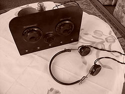
Regenerative circuit
Encyclopedia

Vacuum tube
In electronics, a vacuum tube, electron tube , or thermionic valve , reduced to simply "tube" or "valve" in everyday parlance, is a device that relies on the flow of electric current through a vacuum...
or other active component
Electrical element
Electrical elements are conceptual abstractions representing idealized electrical components, such as resistors, capacitors, and inductors, used in the analysis of electrical networks...
such as a field effect transistor. It consists of an amplifying vacuum tube or transistor with its output connected to its input through a feedback loop, providing positive feedback
Positive feedback
Positive feedback is a process in which the effects of a small disturbance on a system include an increase in the magnitude of the perturbation. That is, A produces more of B which in turn produces more of A. In contrast, a system that responds to a perturbation in a way that reduces its effect is...
. This circuit was widely used in radio receivers, called regenerative receivers, between 1920 and World War II
World War II
World War II, or the Second World War , was a global conflict lasting from 1939 to 1945, involving most of the world's nations—including all of the great powers—eventually forming two opposing military alliances: the Allies and the Axis...
. Regenerative receiver circuits are still used in low-cost electronic equipment such as garage door opener
Garage door opener
A garage door opener is a motorized device that opens and closes garage doors. Most are controlled by switches on the garage wall, as well as by remote controls carried in the garage owner's cars, or more rarely, on keychains.- The electric opener :...
s.
How it works
Radio frequency
Radio frequency is a rate of oscillation in the range of about 3 kHz to 300 GHz, which corresponds to the frequency of radio waves, and the alternating currents which carry radio signals...
feedback oscillator topology can be operated as a regenerative receiver if modified to provide a controllable reduction in feedback loop coupling, a method of coupling the loop to an incoming signal source, and a method of coupling audio frequencies out of the loop to a subsequent audio amplification stage (or high efficiency headphones). It functions as a combination of an oscillator and mixer
Frequency mixer
In electronics a mixer or frequency mixer is a nonlinear electrical circuit that creates new frequencies from two signals applied to it. In its most common application, two signals at frequencies f1 and f2 are applied to a mixer, and it produces new signals at the sum f1 + f2 and difference f1 -...
which converts the modulation directly to the audio baseband.
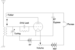
Because of the large amplification possible with regeneration, regenerative receivers often use only a single amplifying element (tube or transistor). In a regenerative receiver the output of the tube or transistor is connected to its input through a feedback loop with a tuned circuit (LC circuit) as a filter in it. The tuned circuit allows positive feedback only at its resonant frequency. The tuned circuit is also connected to the antenna and serves to select the radio frequency to be received, and is adjustable to tune in different stations. The feedback loop also has a means of adjusting the amount of feedback (the loop gain
Loop gain
Loop gain is an engineering term used to quantify the gain of a system controlled by feedback loops. As such, the concept of loop gain is useful in a variety of disciplines. Traditionally, most of those have been in the field of electronics, telecommunications, or control systems...
). For AM signals the tube also functions as a detector
Detector (radio)
A detector is a device that recovers information of interest contained in a modulated wave. The term dates from the early days of radio when all transmissions were in Morse code, and it was only necessary to detect the presence of a radio wave using a device such as a coherer without necessarily...
, rectifying
Rectification
Rectification has the following technical meanings:* Rectification, in astrology* Rectification , a concept found in biology and industrial chemistry* Chinese history: see Cheng Feng...
the RF signal to recover the audio
Audio signal
An audio signal is an analog representation of sound, typically as an electrical voltage. Audio signals may be synthesized directly, or may originate at a transducer such as a microphone, musical instrument pickup, phonograph cartridge, or tape head. Loudspeakers or headphones convert an electrical...
modulation
Modulation
In electronics and telecommunications, modulation is the process of varying one or more properties of a high-frequency periodic waveform, called the carrier signal, with a modulating signal which typically contains information to be transmitted...
; for this reason the circuit is also called a regenerative detector.
For AM
Amplitude modulation
Amplitude modulation is a technique used in electronic communication, most commonly for transmitting information via a radio carrier wave. AM works by varying the strength of the transmitted signal in relation to the information being sent...
reception, the gain of the loop is adjusted so it is just below the level required for oscillation
Oscillation
Oscillation is the repetitive variation, typically in time, of some measure about a central value or between two or more different states. Familiar examples include a swinging pendulum and AC power. The term vibration is sometimes used more narrowly to mean a mechanical oscillation but sometimes...
(a loop gain of just less than one). The result of this is to increase the gain
Gain
In electronics, gain is a measure of the ability of a circuit to increase the power or amplitude of a signal from the input to the output. It is usually defined as the mean ratio of the signal output of a system to the signal input of the same system. It may also be defined on a logarithmic scale,...
of the amplifier by a large factor at the bandpass frequency (resonant frequency), while not increasing it at other frequencies. So the incoming radio signal is amplified by a large amount, 103 - 105, increasing the receiver's sensitivity to weak signals. The high gain also has the effect of sharpening the circuit's bandwidth
Bandwidth
Bandwidth is the difference between the upper and lower frequencies in a contiguous set of frequencies. It is typically measured in hertz, and may sometimes refer to passband bandwidth, sometimes to baseband bandwidth, depending on context...
(increasing the Q factor
Q factor
In physics and engineering the quality factor or Q factor is a dimensionless parameter that describes how under-damped an oscillator or resonator is, or equivalently, characterizes a resonator's bandwidth relative to its center frequency....
) by an equal factor, increasing the selectivity
Electronic selectivity
Selectivity is a measure of the performance of a radio receiver to respond only to the radio signal it is tuned to and reject other signals nearby in frequency, such as another broadcast on an adjacent channel....
of the receiver, its ability to reject interfering signals at frequencies near the desired station's frequency.
For the reception of CW
Continuous wave
A continuous wave or continuous waveform is an electromagnetic wave of constant amplitude and frequency; and in mathematical analysis, of infinite duration. Continuous wave is also the name given to an early method of radio transmission, in which a carrier wave is switched on and off...
radiotelegraphy (Morse code
Morse code
Morse code is a method of transmitting textual information as a series of on-off tones, lights, or clicks that can be directly understood by a skilled listener or observer without special equipment...
) signals, the feedback is increased above the level of oscillation (a loop gain of one), so that the amplifier functions as an oscillator
Electronic oscillator
An electronic oscillator is an electronic circuit that produces a repetitive electronic signal, often a sine wave or a square wave. They are widely used in innumerable electronic devices...
(BFO) as well as an amplifier, generating a steady sine wave
Sine wave
The sine wave or sinusoid is a mathematical function that describes a smooth repetitive oscillation. It occurs often in pure mathematics, as well as physics, signal processing, electrical engineering and many other fields...
signal at the resonant frequency, as well as amplifying the incoming signal. The tuned circuit is adjusted so the oscillator frequency is a little to one side of the signal frequency. The two frequencies mix in the amplifier, generating a beat frequency signal at the difference between the two frequencies. This frequency is in the audio
Audio frequency
An audio frequency or audible frequency is characterized as a periodic vibration whose frequency is audible to the average human...
range, so it is heard as a steady tone in the receiver's speaker whenever the station's carrier
Carrier wave
In telecommunications, a carrier wave or carrier is a waveform that is modulated with an input signal for the purpose of conveying information. This carrier wave is usually a much higher frequency than the input signal...
is present. Morse code is transmitted by keying the transmitter on and off, producing different length pulses of carrier ("dots" and "dashes"). The audio tone makes the carrier pulses audible, and they are heard as "beeps" in the speaker.
For the reception of single-sideband
Single-sideband modulation
Single-sideband modulation or Single-sideband suppressed-carrier is a refinement of amplitude modulation that more efficiently uses electrical power and bandwidth....
signals, the circuit is also set to oscillate. The BFO signal is adjusted to one side of the incoming signal, and functions as the replacement carrier needed to demodulate the signal.
Description
Regenerative receivers require fewer components than other types of receiver circuit. The circuit's original attraction was that it got more amplification (gainGain
In electronics, gain is a measure of the ability of a circuit to increase the power or amplitude of a signal from the input to the output. It is usually defined as the mean ratio of the signal output of a system to the signal input of the same system. It may also be defined on a logarithmic scale,...
) out of the expensive vacuum tube
Vacuum tube
In electronics, a vacuum tube, electron tube , or thermionic valve , reduced to simply "tube" or "valve" in everyday parlance, is a device that relies on the flow of electric current through a vacuum...
s of early receivers, thus requiring fewer stages of amplification. Early vacuum tubes had low gain at radio frequencies
Radio frequency
Radio frequency is a rate of oscillation in the range of about 3 kHz to 300 GHz, which corresponds to the frequency of radio waves, and the alternating currents which carry radio signals...
(RF). Therefore the TRF receivers
Tuned radio frequency receiver
A tuned radio frequency receiver is a radio receiver that is usually composed of several tuned radio frequency amplifiers followed by circuits to detect and amplify the audio signal. Prevalent in the early 20th century, it can be difficult to operate because each stage must be individually tuned...
used before regenerative receivers often required 5 or 6 tubes, each stage requiring tuned circuits that had to be tuned in tandem to bring in stations, making the receiver cumbersome, power hungry, and hard to adjust. Regenerative receivers, by contrast, could often get adequate gain with one tube. In the 1930s the regenerative receiver was replaced by the superheterodyne circuit in commercial receivers due to its superior performance and the falling cost of tubes. Transistor
Transistor
A transistor is a semiconductor device used to amplify and switch electronic signals and power. It is composed of a semiconductor material with at least three terminals for connection to an external circuit. A voltage or current applied to one pair of the transistor's terminals changes the current...
s, either bipolar or JFETs are used in regenerative receivers today. In recent years the regenerative circuit has seen a modest comeback in receivers for low cost digital radio
Digital radio
Digital radio has several meanings:1. Today the most common meaning is digital radio broadcasting technologies, such as the digital audio broadcasting system, also known as Eureka 147. In these systems, the analog audio signal is digitized into zeros and ones, compressed using formats such as...
applications such as garage door opener
Garage door opener
A garage door opener is a motorized device that opens and closes garage doors. Most are controlled by switches on the garage wall, as well as by remote controls carried in the garage owner's cars, or more rarely, on keychains.- The electric opener :...
s, keyless locks, RFID readers, some cell phone receivers.
Regeneration can increase the gain of an amplifier by a factor of 15,000 or more. This is quite an improvement, especially for the low-gain vacuum tubes of the 1920s and early 1930s. The type 236 triode (US vacuum tube, obsolete since the mid-1930s) had a non-regenerative voltage gain of only 9.2 at 7.2 MHz, but in a regenerative detector, had voltage gain as high as 7900. In general, "... regenerative amplification as found to be nearly directly proportional to the non-regenerative detection gain." "... the regenerative amplification is limited by the stability of the circuit elements, tube [or device] characteristics and [stability of] supply voltages which determine the maximum value of regeneration obtainable without self-oscilation." Intrinsically, there is little or no difference in the gain and stability available from vacuum tubes, JFET's MOSFET's or bipolar junction transistors (BJT's).
A disadvantage of this receiver is that the regeneration (feedback) level must be adjusted when it is tuned to a new station. This is because the regenerative detector has less gain with stronger signals, and because the stronger signals cause the tube or transistor to operate on a different section of its amplification curve (i.e. grid V vs. plate V for tubes; gate V vs drain V for FET's, and base current vs. collector current for BJT's).
A drawback of early vacuum tube designs was that, when the circuit was adjusted to oscillate, it could operate as a transmitter, radiating an RF signal from its antenna at power levels as high as one watt. So it often caused interference
RFI
RFI can mean:* Rowing Federation of India* Radio Frequency Interference* Radio France Internationale* Remote File Inclusion* Request for information, a business process* Rete Ferroviaria Italiana...
to nearby receivers. Modern circuits using semiconductor
Semiconductor
A semiconductor is a material with electrical conductivity due to electron flow intermediate in magnitude between that of a conductor and an insulator. This means a conductivity roughly in the range of 103 to 10−8 siemens per centimeter...
s, or high-gain vacuum tubes with plate voltage as low as 12V, typically operate at milliwatt levels—one thousand times lower. So interference is far less of a problem today. In any case, adding a preamp stage (RF stage) between the antenna and the regenerative detector is often used to further lower the interference.
Other shortcomings of regenerative receivers are the presence of a characteristic noise (“mush”) in their audio output, and sensitive and unstable tuning. These problems have the same cause: a regenerative receiver’s gain is greatest when it operates on the verge of oscillation, and in that condition, the circuit behaves chaotically
Chaos theory
Chaos theory is a field of study in mathematics, with applications in several disciplines including physics, economics, biology, and philosophy. Chaos theory studies the behavior of dynamical systems that are highly sensitive to initial conditions, an effect which is popularly referred to as the...
. Simple regenerative receivers lack an RF amplifier between the antenna and the regenerative detectors, so any change with the antenna swaying in the wind, etc. can change the frequency of the detector.
A major improvement in stability and a small improvement in available gain is the use of a separate oscillator, which separates the oscillator and its frequency from the rest of the receiver, and also allows the regenerative detector to be set for maximum gain and selectivity - which is always in the non-oscillating condition. A separate oscillator, sometimes called a BFO (Beat Frequency Oscillator) was known from the early days of radio, but was rarely used to improve the regenerative detector. When the regenerative detector is used in the self-oscillating mode, i.e. without a separate oscillator, it is known as an "autodyne".
History
The inventor of FMFM broadcasting
FM broadcasting is a broadcasting technology pioneered by Edwin Howard Armstrong which uses frequency modulation to provide high-fidelity sound over broadcast radio. The term "FM band" describes the "frequency band in which FM is used for broadcasting"...
radio, Edwin Armstrong
Edwin Armstrong
Edwin Howard Armstrong was an American electrical engineer and inventor. Armstrong was the inventor of modern frequency modulation radio....
, invented and patented the regenerative circuit while he was a junior in college, in 1914. He patented the super-regenerative circuit in 1922, and the superheterodyne receiver in 1918.
Lee De Forest
Lee De Forest
Lee De Forest was an American inventor with over 180 patents to his credit. De Forest invented the Audion, a vacuum tube that takes relatively weak electrical signals and amplifies them. De Forest is one of the fathers of the "electronic age", as the Audion helped to usher in the widespread use...
filed a patent in 1916 that became the cause of a contentious lawsuit with the prolific inventor Armstrong, whose patent for the regenerative circuit had been issued in 1914. The lawsuit lasted twelve years, winding its way through the appeals process and ending up at the Supreme Court
Supreme Court of the United States
The Supreme Court of the United States is the highest court in the United States. It has ultimate appellate jurisdiction over all state and federal courts, and original jurisdiction over a small range of cases...
. Every court up to the Supreme Court had ruled in favor of Armstrong. However, the Supreme Court ruled in favor of De Forest.
At the time the regenerative receiver was introduced, vacuum tube
Vacuum tube
In electronics, a vacuum tube, electron tube , or thermionic valve , reduced to simply "tube" or "valve" in everyday parlance, is a device that relies on the flow of electric current through a vacuum...
s were expensive and consumed lots of power, with the added expense and encumbrance of heavy batteries or AC transformer
Transformer
A transformer is a device that transfers electrical energy from one circuit to another through inductively coupled conductors—the transformer's coils. A varying current in the first or primary winding creates a varying magnetic flux in the transformer's core and thus a varying magnetic field...
and rectifier
Rectifier
A rectifier is an electrical device that converts alternating current , which periodically reverses direction, to direct current , which flows in only one direction. The process is known as rectification...
. So this design, getting most gain out of one tube, filled the needs of the growing radio community and immediately thrived. Although the superheterodyne receiver is the most common receiver in use today, the regenerative radio made the most out of very few parts.
In World War II the regenerative circuit was used in some military equipment. An example is the German field radio "Torn.E.b". Regenerative receivers needed far fewer tubes and less power consumption for nearly equivalent performance.
A related circuit, the super-regenerative detector, found several highly-important military uses in World War II in Friend or Foe
Secondary surveillance radar
Secondary surveillance radar is a radar system used in air traffic control , that not only detects and measures the position of aircraft i.e. range and bearing, but also requests additional information from the aircraft itself such as its identity and altitude...
identification equipment and in the top-secret proximity fuse.
In the 1930s, the superheterodyne design began to gradually supplant the regenerative receiver, as tubes became far less expensive. In Germany the design was still used in the millions of mass-produced German "peoples receivers" (Volksempfänger
Volksempfänger
The Volksempfänger was a range of radio receivers developed by engineer Otto Griessing at the request of Propaganda Minister Joseph Goebbels....
) and "German small receivers" (DKE, Deutscher Kleinempfänger). Even after WWII, the regenerative design was still present in early after-war German minimal designs along the lines of the "peoples receivers" and "small receivers", dictated by lack of materials. Frequently German military tubes like the "RV12P2000" were employed in such designs. There were even superheterodyne designs, which used the regenerative receiver as a combined IF and demodulator with fixed regeneration. The superregenerative design was also present in early FM broadcast receivers around 1950. Later it was almost completely phased out of mass production, remaining only in hobby kits.
Operating limits
Quality of a receiver is defined by its sensitivity and selectivity. For a single-tank TRF (tuned radio frequency) receiverTuned radio frequency receiver
A tuned radio frequency receiver is a radio receiver that is usually composed of several tuned radio frequency amplifiers followed by circuits to detect and amplify the audio signal. Prevalent in the early 20th century, it can be difficult to operate because each stage must be individually tuned...
without regenerative feedback,
 , where Q is tank "quality" defined as
  , Z is reactive impedance, R is resistive loss. Signal voltage at tank is antenna voltage multiplied by Q.
Positive feedback compensates the energy loss caused by R, so we may express it as bringing in some negative R. Quality with feedback is
 . Regeneration rate is
  .
.M depends on stability of amplification and feedback coefficient, because if R-Rneg is set less than Rneg fluctuation, it will easily overstep the oscillation margin. This problem can be partly solved by "grid leak" or any kind of automatic gain control, but the downside of this is surrendering control over receiver to noises and fadings of input signal, which is undesirable. Modern semiconductors may offer more stability than vacuum tubes of the 1920s, depending on other circuit parameters as well.
Actual numbers:
To have 3 kHz bandwidth at 12 MHz (short waves travelling all around Earth) we need
 . A two-inch coil of thick silvered wire wound on a ceramic core may have Q up to 400, but let's suppose Q = 100. We need M = 40, which is attainable with good stable amplifier even without power stabilizing.
Super-regenerative receiver
The super-regenerative receiver uses a second lower frequency oscillation (within the same stage or by using a second oscillator stage) to provide single-device circuit gains of around one million. This second oscillation periodically interrupts or "quenches" the main RF oscillation. Ultrasonic quench rates between 30 and 100 kHz are typical. After each quenching, RF oscillation grows exponentially, starting from the tiny energy picked-up by the antenna plus circuit noise. The amplitude reached at the end of the quench cycle (linear mode) or the time taken to reach limiting amplitude (log mode) depends on the strength of the received signal from which exponential growth started. A low-pass filterLow-pass filter
A low-pass filter is an electronic filter that passes low-frequency signals but attenuates signals with frequencies higher than the cutoff frequency. The actual amount of attenuation for each frequency varies from filter to filter. It is sometimes called a high-cut filter, or treble cut filter...
in the audio amplifier filters the quench and RF frequencies from the output, leaving the AM modulation. This provides a crude but very effective AGC (Automatic Gain Control).
Types of Signals for Regenerative vs. Super-Regenerative (super-regen or superregen) Detectors.
Super-Regenerative Detectors work well for wide-band signals such as FM, where it performs "slope detection". Regenerative Detectors work well for narrow-band signals, especially for CW and SSB which need a heterodyne oscillator or BFO. A super-regenerative detector does not have a usable heterodyne oscillator - even though the super-regen always self-oscillates, so CW (Morse Code)and SSB (Single side band) signals can't be received properly.
Super-regeneration is most valuable above 27 MHz, and for signals where broad tuning is desirable. The super-regen uses far fewer components for nearly the same sensitivity as more complex designs. It is easily possible to build super-regen receivers which operate at microwatt power levels, in the 30 to 6,000 MHz range. These are ideal for remote-sensing applications or where long battery life is important. For many years, super regenerative circuits have been used for commercial products such as garage-door openers, radar detectors, microwatt RF data links, and very low cost walkie-talkies.
Because the super-regenerative detectors tend to receive the strongest signal and ignore other signals in the nearby spectrum, the super-regen works best with bands that are relatively free of interfering signals. Due to Nyquist's theorem its quenching frequency must be at least twice the signal bandwidth. But quenching with overtones acts further as a heterodyne
Heterodyne
Heterodyning is a radio signal processing technique invented in 1901 by Canadian inventor-engineer Reginald Fessenden where high frequency signals are converted to lower frequencies by combining two frequencies. Heterodyning is useful for frequency shifting information of interest into a useful...
receiver mixing additional unneeded signals from those bands into the working frequency. Thus the overall bandwidth of super-regenerator cannot be less than 4 times that of the quench frequency, assuming the quenching oscillator produces an ideal sinewave.
Patents
- Armstrong, E. H., , Wireless receiving system, 1914.
- Armstrong, E. H., , Method of receiving high frequency oscillation, 1922.
- Armstrong, E. H., , Signalling system, 1922.
- Braden, R. A., , Superregenerative magnetron receiver, 1940.
External links
- Some Recent Developments in the Audion Receiver by EH Armstrong, Proceedings of the IRE (Institute of Radio EngineersInstitute of Radio EngineersThe Institute of Radio Engineers was a professional organization which existed from 1912 until January 1, 1963, when it merged with the American Institute of Electrical Engineers to form the Institute of Electrical and Electronics Engineers .-Founding:Following several attempts to form a...
), volume 3, 1915, pp. 215–247. - a one transistor regenerative receiver