
Pierce oscillator
Encyclopedia
The Pierce oscillator is a type of electronic oscillator
particularly well-suited for use in piezoelectric crystal oscillator
circuits. Named for its inventor, George W. Pierce
(1872-1956), the Pierce oscillator is a derivative of the Colpitts oscillator
. Virtually all digital IC clock oscillators are of Pierce type, as the circuit can be implemented using a minimum of components: a single digital inverter
, two resistors, two capacitors, and the quartz crystal, which acts as a highly selective filter element. The low manufacturing cost of this circuit, and the outstanding frequency stability of the quartz crystal, give it an advantage over other designs in many consumer electronics
applications.
resistor
, biasing the inverter in its linear
region of operation and effectively causing it to function as a high gain inverting amplifier
.
To see this, assume the inverter is ideal, with infinite input impedance
and zero output impedance
. The resistor forces the input and output voltages to be equal. Hence the inverter will neither be fully on nor fully off, but will operate in the transition region where it has gain.
, which provides a 180 degree phase shift and a voltage gain from the output to input at approximately the resonant frequency of the crystal. To understand the operation, note that at the frequency of oscillation, the crystal appears inductive. Thus, it can be considered a large, high Q inductor. The combination of the 180 degree phase shift (i.e. inverting gain) from the pi network, and the negative gain from the inverter, results in a positive loop gain (positive feedback
), making the bias point set by R1 unstable and leading to oscillation.
The series resistor Rs reduces the chance of overtone oscillation and can improve start-up time.
A second resistor could be used between the output of the inverter and the crystal to isolate the inverter from the crystal network. This would also add additional phase shift to C1.
To assure operation at the correct frequency, one must make sure the capacitances in the circuit match the value specified on the crystal's data sheet. Load capacitance CL can be calculated from the series combination of C1 and C2, taking into account Ci and Co, the input and output capacitance of the inverter, and Cs, the stray capacitances from the oscillator, PCB layout, and crystal case (typically 3-9 pF):
When a "series" crystal is used in a Pierce oscillator, the Pierce oscillator (as always) drives the crystal at nearly its parallel resonance frequency. But that frequency is few kilohertz higher than the series resonant frequency printed on the package of a "series" crystal. Increasing the "load capacitance" slightly decreases the frequency generated by a Pierce oscillator, but never enough to reduce it all the way down to the series resonant frequency.
Electronic oscillator
An electronic oscillator is an electronic circuit that produces a repetitive electronic signal, often a sine wave or a square wave. They are widely used in innumerable electronic devices...
particularly well-suited for use in piezoelectric crystal oscillator
Crystal oscillator
A crystal oscillator is an electronic oscillator circuit that uses the mechanical resonance of a vibrating crystal of piezoelectric material to create an electrical signal with a very precise frequency...
circuits. Named for its inventor, George W. Pierce
G. W. Pierce
George Washington Pierce was an American physicist. He was a professor of physics at Harvard University and inventor in the development of electronic telecommunications....
(1872-1956), the Pierce oscillator is a derivative of the Colpitts oscillator
Colpitts oscillator
A Colpitts oscillator, invented in 1920 by American engineer Edwin H. Colpitts, is one of a number of designs for electronic oscillator circuits using the combination of an inductance with a capacitor for frequency determination, thus also called LC oscillator...
. Virtually all digital IC clock oscillators are of Pierce type, as the circuit can be implemented using a minimum of components: a single digital inverter
Inverter (logic gate)
In digital logic, an inverter or NOT gate is a logic gate which implements logical negation. The truth table is shown on the right.This represents perfect switching behavior, which is the defining assumption in Digital electronics. In practice, actual devices have electrical characteristics that...
, two resistors, two capacitors, and the quartz crystal, which acts as a highly selective filter element. The low manufacturing cost of this circuit, and the outstanding frequency stability of the quartz crystal, give it an advantage over other designs in many consumer electronics
Consumer electronics
Consumer electronics are electronic equipment intended for everyday use, most often in entertainment, communications and office productivity. Radio broadcasting in the early 20th century brought the first major consumer product, the broadcast receiver...
applications.
Biasing resistor
R1 acts as a feedbackFeedback
Feedback describes the situation when output from an event or phenomenon in the past will influence an occurrence or occurrences of the same Feedback describes the situation when output from (or information about the result of) an event or phenomenon in the past will influence an occurrence or...
resistor
Resistor
A linear resistor is a linear, passive two-terminal electrical component that implements electrical resistance as a circuit element.The current through a resistor is in direct proportion to the voltage across the resistor's terminals. Thus, the ratio of the voltage applied across a resistor's...
, biasing the inverter in its linear
Linear
In mathematics, a linear map or function f is a function which satisfies the following two properties:* Additivity : f = f + f...
region of operation and effectively causing it to function as a high gain inverting amplifier
Amplifier
Generally, an amplifier or simply amp, is a device for increasing the power of a signal.In popular use, the term usually describes an electronic amplifier, in which the input "signal" is usually a voltage or a current. In audio applications, amplifiers drive the loudspeakers used in PA systems to...
.
To see this, assume the inverter is ideal, with infinite input impedance
Input impedance
The input impedance of an electrical network is the equivalent impedance "seen" by a power source connected to that network. If the source provides known voltage and current, such impedance can be calculated using Ohm's Law...
and zero output impedance
Output impedance
The output impedance, source impedance, or internal impedance of an electronic device is the opposition exhibited by its output terminals to an alternating current of a particular frequency as a result of resistance, inductance and capacitance...
. The resistor forces the input and output voltages to be equal. Hence the inverter will neither be fully on nor fully off, but will operate in the transition region where it has gain.
Resonator
The crystal in combination with C1 and C2 forms a pi network band-pass filterBand-pass filter
A band-pass filter is a device that passes frequencies within a certain range and rejects frequencies outside that range.Optical band-pass filters are of common usage....
, which provides a 180 degree phase shift and a voltage gain from the output to input at approximately the resonant frequency of the crystal. To understand the operation, note that at the frequency of oscillation, the crystal appears inductive. Thus, it can be considered a large, high Q inductor. The combination of the 180 degree phase shift (i.e. inverting gain) from the pi network, and the negative gain from the inverter, results in a positive loop gain (positive feedback
Positive feedback
Positive feedback is a process in which the effects of a small disturbance on a system include an increase in the magnitude of the perturbation. That is, A produces more of B which in turn produces more of A. In contrast, a system that responds to a perturbation in a way that reduces its effect is...
), making the bias point set by R1 unstable and leading to oscillation.
Isolation resistor
Ruan Lourens strongly recommends a series resistor Rs between the output of the inverter and the crystal.The series resistor Rs reduces the chance of overtone oscillation and can improve start-up time.
A second resistor could be used between the output of the inverter and the crystal to isolate the inverter from the crystal network. This would also add additional phase shift to C1.
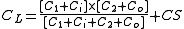
Load capacitance
The total capacitance seen from the crystal looking into the rest of the circuit is called the "load capacitance". When a manufacturer makes a "parallel" crystal, a technician adjusts a Pierce oscillator with a variable capacitor (often 18 or 20 pF) to trim the crystal to oscillate at exactly the frequency written on its package.To assure operation at the correct frequency, one must make sure the capacitances in the circuit match the value specified on the crystal's data sheet. Load capacitance CL can be calculated from the series combination of C1 and C2, taking into account Ci and Co, the input and output capacitance of the inverter, and Cs, the stray capacitances from the oscillator, PCB layout, and crystal case (typically 3-9 pF):
When a "series" crystal is used in a Pierce oscillator, the Pierce oscillator (as always) drives the crystal at nearly its parallel resonance frequency. But that frequency is few kilohertz higher than the series resonant frequency printed on the package of a "series" crystal. Increasing the "load capacitance" slightly decreases the frequency generated by a Pierce oscillator, but never enough to reduce it all the way down to the series resonant frequency.