

Phasor (electronics)
Encyclopedia
Physics
Physics is a natural science that involves the study of matter and its motion through spacetime, along with related concepts such as energy and force. More broadly, it is the general analysis of nature, conducted in order to understand how the universe behaves.Physics is one of the oldest academic...
and engineering
Engineering
Engineering is the discipline, art, skill and profession of acquiring and applying scientific, mathematical, economic, social, and practical knowledge, in order to design and build structures, machines, devices, systems, materials and processes that safely realize improvements to the lives of...
, a phase vector, or phasor, is a representation of a sine wave
Sine wave
The sine wave or sinusoid is a mathematical function that describes a smooth repetitive oscillation. It occurs often in pure mathematics, as well as physics, signal processing, electrical engineering and many other fields...
whose amplitude
Amplitude
Amplitude is the magnitude of change in the oscillating variable with each oscillation within an oscillating system. For example, sound waves in air are oscillations in atmospheric pressure and their amplitudes are proportional to the change in pressure during one oscillation...
(A) and angular frequency
Angular frequency
In physics, angular frequency ω is a scalar measure of rotation rate. Angular frequency is the magnitude of the vector quantity angular velocity...
(ω) are time-invariant. It is a subset of a more general concept called analytic representation
Analytic signal
In mathematics and signal processing, the analytic representation of a real-valued function or signal facilitates many mathematical manipulations of the signal. The basic idea is that the negative frequency components of the Fourier transform of a real-valued function are superfluous, due to the...
. Phasors decompose the behavior of a sinusoid into three independent factors that relay amplitude, frequency and phase information. This can be particularly useful because the frequency factor (which includes the time-dependence of the sine wave) is often common to all the components of a linear combination of sine waves. In these situations, phasors allow this common feature to be factored out, leaving just the time-independent amplitude and phase information (the latter simply defining the phase at t=0 as θ), which can be combined algebraically rather than trigonometrically. Similarly, linear differential equations can be reduced to algebraic
Algebraic
Algebraic may refer to any subject within the algebra branch of mathematics and related branches like algebraic geometry and algebraic topology.Algebraic may also refer to:...
ones. The term phasor therefore often refers to just those two factors. In older texts, a phasor is also referred to as a sinor.
Definition
Euler's formulaEuler's formula
Euler's formula, named after Leonhard Euler, is a mathematical formula in complex analysis that establishes the deep relationship between the trigonometric functions and the complex exponential function...
indicates that sine waves can be represented mathematically as the sum of two complex-valued functions:

or as the real part of one of the functions:
As indicated above, phasor can refer to either
 or just the complex constant,
  . In the latter case, it is understood to be a shorthand notation, encoding the amplitude and phase of an underlying sinusoid.
An even more compact shorthand is angle notation:


 . The phase constant
  represents the angle that the complex vector forms with the real axis at t = 0.
Multiplication by a constant (scalar)
Multiplication of the phasor by a complex constant,
  produces another phasor. That means its only effect is to change the amplitude and phase of the underlying sinusoid:
In electronics,
 would represent an impedance
Electrical impedance
Electrical impedance, or simply impedance, is the measure of the opposition that an electrical circuit presents to the passage of a current when a voltage is applied. In quantitative terms, it is the complex ratio of the voltage to the current in an alternating current circuit...
, which is independent of time. In particular it is not the shorthand notation for another phasor. Multiplying a phasor current by an impedance produces a phasor voltage. But the product of two phasors (or squaring a phasor) would represent the product of two sine waves, which is a non-linear operation that produces new frequency components. Phasor notation can only represent systems with one frequency, such as a linear system stimulated by a sinusoid.
Differentiation and integration
The time derivative or integral of a phasor produces another phasor. For example:
Therefore, in phasor representation, the time derivative of a sinusoid becomes just multiplication by the constant,
 Similarly, integrating a phasor corresponds to multiplication by
  The time-dependent factor,
  , is unaffected. When we solve a linear differential equation
Linear differential equation
Linear differential equations are of the formwhere the differential operator L is a linear operator, y is the unknown function , and the right hand side ƒ is a given function of the same nature as y...
with phasor arithmetic, we are merely factoring
 out of all terms of the equation, and reinserting it into the answer. For example, consider the following differential equation for the voltage across the capacitor in an RC circuit
RC circuit
A resistor–capacitor circuit ', or RC filter or RC network, is an electric circuit composed of resistors and capacitors driven by a voltage or current source...
:
When the voltage source in this circuit is sinusoidal:
we may substitute:
where phasor
 and phasor
  is the unknown quantity to be determined.
In the phasor shorthand notation, the differential equation reduces to:
Solving for the phasor capacitor voltage gives:
As we have seen, the factor multiplying
 represents differences of the amplitude and phase of
  relative to
  and
and 
In polar coordinate form, it is:

Therefore:
Addition
where:

or, via the law of cosines
Law of cosines
In trigonometry, the law of cosines relates the lengths of the sides of a plane triangle to the cosine of one of its angles. Using notation as in Fig...
on the complex plane
Complex plane
In mathematics, the complex plane or z-plane is a geometric representation of the complex numbers established by the real axis and the orthogonal imaginary axis...
(or the trigonometric identity for angle differences):

where
 .
.A key point is that A3 and θ3 do not depend on ω or t, which is what makes phasor notation possible. The time and frequency dependence can be suppressed and re-inserted into the outcome as long as the only operations used in between are ones that produce another phasor. In angle notation, the operation shown above is written:

Another way to view addition is that two vectors with coordinates and are added vectorially to produce a resultant vector with coordinates . (see animation)
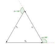
Triangle
A triangle is one of the basic shapes of geometry: a polygon with three corners or vertices and three sides or edges which are line segments. A triangle with vertices A, B, and C is denoted ....
, so the angle between each phasor to the next is 120° (2π/3 radians), or one third of a wavelength /3. So the phase difference between each wave must also be 120°, as is the case in three-phase power
In other words, what this shows is:

In the example of three waves, the phase difference between the first and the last wave was 240 degrees, while for two waves destructive interference happens at 180 degrees. In the limit of many waves, the phasors must form a circle for destructive interference, so that the first phasor is nearly parallel with the last. This means that for many sources, destructive interference happens when the first and last wave differ by 360 degrees, a full wavelength
 . This is why in single slit diffraction
Diffraction
Diffraction refers to various phenomena which occur when a wave encounters an obstacle. Italian scientist Francesco Maria Grimaldi coined the word "diffraction" and was the first to record accurate observations of the phenomenon in 1665...
, the minima occurs when light
Light
Light or visible light is electromagnetic radiation that is visible to the human eye, and is responsible for the sense of sight. Visible light has wavelength in a range from about 380 nanometres to about 740 nm, with a frequency range of about 405 THz to 790 THz...
from the far edge travels a full wavelength further than the light from the near edge.
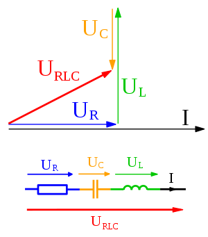
Phasor diagrams
Electrical engineers, electronics engineers, electronic engineering technicians and aircraft engineers all use phasor diagrams to visualize complex constants and variables (phasors). Like vectors, arrows drawn on graph paper or computer displays represent phasors. Cartesian and polar representations each have advantages.Circuit laws
With phasors, the techniques for solving DCDirect current
Direct current is the unidirectional flow of electric charge. Direct current is produced by such sources as batteries, thermocouples, solar cells, and commutator-type electric machines of the dynamo type. Direct current may flow in a conductor such as a wire, but can also flow through...
circuits can be applied to solve AC circuits. A list of the basic laws is given below.
- Ohm's law for resistors: a resistor has no time delays and therefore doesn't change the phase of a signal therefore V=IR remains valid.
- Ohm's law for resistors, inductors, and capacitors: V = IZ where Z is the complex impedanceElectrical impedanceElectrical impedance, or simply impedance, is the measure of the opposition that an electrical circuit presents to the passage of a current when a voltage is applied. In quantitative terms, it is the complex ratio of the voltage to the current in an alternating current circuit...
. - In an AC circuit we have real power (P) which is a representation of the average power into the circuit and reactive power (Q) which indicates power flowing back and forward. We can also define the complex power S = P + jQ and the apparent power which is the magnitude of S. The power law for an AC circuit expressed in phasors is then S = VI* (where I* is the complex conjugateComplex conjugateIn mathematics, complex conjugates are a pair of complex numbers, both having the same real part, but with imaginary parts of equal magnitude and opposite signs...
of I). - Kirchhoff's circuit lawsKirchhoff's circuit lawsKirchhoff's circuit laws are two equalities that deal with the conservation of charge and energy in electrical circuits, and were first described in 1845 by Gustav Kirchhoff...
work with phasors in complex form
Given this we can apply the techniques of analysis of resistive circuits
Analysis of resistive circuits
A network, in the context of electronics, is a collection of interconnected components. Network analysis is the process of finding the voltages across, and the currents through, every component in the network. There are a number of different techniques for achieving this...
with phasors to analyze single frequency AC circuits containing resistors, capacitors, and inductors. Multiple frequency linear AC circuits and AC circuits with different waveforms can be analyzed to find voltages and currents by transforming all waveforms to sine wave components with magnitude and phase then analyzing each frequency separately, as allowed by the superposition theorem
Superposition theorem
The superposition theorem for electrical circuits states that the response in any branch of a bilateral linear circuit having more than one independent source equals the algebraic sum of the responses caused by each independent source acting alone, while all other independent sources are replaced...
.
Power engineering
In analysis of three phase AC power systems, usually a set of phasors is defined as the three complex cube roots of unity, graphically represented as unit magnitudes at angles of 0, 120 and 240 degrees. By treating polyphase AC circuit quantities as phasors, balanced circuits can be simplified and unbalanced circuits can be treated as an algebraic combination of symmetrical circuits. This approach greatly simplifies the work required in electrical calculations of voltage drop, power flow, and short-circuit currents. In the context of power systems analysis, the phase angle is often given in degreeDegree (angle)
A degree , usually denoted by ° , is a measurement of plane angle, representing 1⁄360 of a full rotation; one degree is equivalent to π/180 radians...
s, and the magnitude in rms
Root mean square
In mathematics, the root mean square , also known as the quadratic mean, is a statistical measure of the magnitude of a varying quantity. It is especially useful when variates are positive and negative, e.g., sinusoids...
value rather than the peak amplitude of the sinusoid.
The technique of synchrophasor
Synchrophasor
A phasor measurement unit is a device which measures the electrical waves on an electricity grid, using a common time source for synchronization. Time synchronization allows synchronized real-time measurements of multiple remote measurement points on the grid...
s uses digital instruments to measure the phasors representing transmission system voltages at widespread points in a transmission network. Small changes in the phasors are sensitive indicators of power flow and system stability.