
Perspective projection distortion
Encyclopedia
Perspective projection distortion is the inevitable misrepresentation of three-dimensional space when drawn or "projected" onto a two-dimensional surface.
It is impossible to accurately depict 3D reality on a 2D plane. However, there are several constructs available which allow for seemingly accurate representation. The most common of these is perspective projection. Perspective projection can be used to mirror how the eye sees by the use of one or more vanishing points
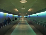
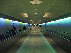
. The typical example is a set of train tracks. When one looks down a stretch of tracks they appear to converge on the horizon, while in reality the rails remain parallel.
’s perspectival demonstrations galvanized the widespread use of convergent perspective of the Renaissance
proper.
 "Artificial perspective projection" was the name given by Leonardo da Vinci
to what today is called "classical perspective projection" and referred to above as the result of a geometric protocol. "Natural perspective projection" was the name given by Leonardo to the projection that produces the large image beheld by the human eye, which is impossible to replicate on a plane surface.
Both types of projection involve a distortion; parallel lines never intersect in nature, but they almost always intersect in perspective projections. The rare exceptions are when a) the surface of projection is planar and b) a plane of the projected object is parallel to the plane of projection.
The difference between the images of the same object produced by "artificial" perspective projection and by "natural" perspective projection is called "perspective distortion." This discussion preserves the Leonardo designation, "artificial" projection, in place of "classical" projection so as to acknowledge Leonardo’s observations that that classical perspective projection produces an image which is different from that beheld by the human eye.
are imaginary lines which aid in the drawing of real images. In photography, the projection mechanism is light reflected from an object.
To execute a drawing using perspective projection projectors emanate from all points of an object and intersect at a station point
. These projectors intersect with an imaginary plane of projection and an image is created on the plane by the points of intersection. The resulting image on the projection plane reproduces the image of the object as it is beheld from the station point.
In the special case—and the only instance—in which an artificial perspective image appears the same to the eye as does a natural perspective image, the eye must view the artificial perspective image from precisely the spatial station point, i.e., from the station point as it is located in actual space.
It is impossible to accurately depict 3D reality on a 2D plane. However, there are several constructs available which allow for seemingly accurate representation. The most common of these is perspective projection. Perspective projection can be used to mirror how the eye sees by the use of one or more vanishing points
Vanishing point
A vanishing point is a point in a perspective drawing to which parallel lines not parallel to the image plane appear to converge. The number and placement of the vanishing points determines which perspective technique is being used...
. The typical example is a set of train tracks. When one looks down a stretch of tracks they appear to converge on the horizon, while in reality the rails remain parallel.
Historical development
The physiological basis of visual foreshortening was undefined until the year 1000 when the Arabian mathematician and philosopher, Alhazen, in his Perspectiva, first explained that light projects conically into the eye. A method for presenting foreshortened geometry systematically onto a plane surface was unknown for another 300 years. The artist Giotto may have been the first to recognize that the image beheld by the eye is distorted: to the eye, parallel lines appear to intersect, (like the distant edges of a path or road) whereas in "undistorted" nature, they do not. One of the first uses of perspective was in Giotto’s Jesus Before the Caïf, more than 100 years before BrunelleschiFilippo Brunelleschi
Filippo Brunelleschi was one of the foremost architects and engineers of the Italian Renaissance. He is perhaps most famous for inventing linear perspective and designing the dome of the Florence Cathedral, but his accomplishments also included bronze artwork, architecture , mathematics,...
’s perspectival demonstrations galvanized the widespread use of convergent perspective of the Renaissance
Renaissance
The Renaissance was a cultural movement that spanned roughly the 14th to the 17th century, beginning in Italy in the Late Middle Ages and later spreading to the rest of Europe. The term is also used more loosely to refer to the historical era, but since the changes of the Renaissance were not...
proper.
Leonardo da Vinci
Leonardo di ser Piero da Vinci was an Italian Renaissance polymath: painter, sculptor, architect, musician, scientist, mathematician, engineer, inventor, anatomist, geologist, cartographer, botanist and writer whose genius, perhaps more than that of any other figure, epitomized the Renaissance...
to what today is called "classical perspective projection" and referred to above as the result of a geometric protocol. "Natural perspective projection" was the name given by Leonardo to the projection that produces the large image beheld by the human eye, which is impossible to replicate on a plane surface.
Both types of projection involve a distortion; parallel lines never intersect in nature, but they almost always intersect in perspective projections. The rare exceptions are when a) the surface of projection is planar and b) a plane of the projected object is parallel to the plane of projection.
The difference between the images of the same object produced by "artificial" perspective projection and by "natural" perspective projection is called "perspective distortion." This discussion preserves the Leonardo designation, "artificial" projection, in place of "classical" projection so as to acknowledge Leonardo’s observations that that classical perspective projection produces an image which is different from that beheld by the human eye.
Distortion in drawing
In a drawing, projectorsGraphical projection
Graphical projection is a protocol by which an image of a three-dimensional object is projected onto a planar surface without the aid of mathematical calculation, used in technical drawing.- Overview :...
are imaginary lines which aid in the drawing of real images. In photography, the projection mechanism is light reflected from an object.
To execute a drawing using perspective projection projectors emanate from all points of an object and intersect at a station point
Station point
A station point is a location or vantage point from which an artist or exhibitor intends an observer to experience an artwork.In photography, the station point is the location of the camera at the point in time when the camera records a view to a recording medium....
. These projectors intersect with an imaginary plane of projection and an image is created on the plane by the points of intersection. The resulting image on the projection plane reproduces the image of the object as it is beheld from the station point.
Distortion caused by projection
Figures 1-3 show the principle of an artificial perspective projection. The artificial perspective projection image appears upon the projection plane (P). Imagine a human eye is placed at the station point (S). This human eye views both the object and the image of the object as if the projection plane did not exist. That is to say, to the eye, from the station point (only) the image of the object is indistinguishable from the object itself.In the special case—and the only instance—in which an artificial perspective image appears the same to the eye as does a natural perspective image, the eye must view the artificial perspective image from precisely the spatial station point, i.e., from the station point as it is located in actual space.
To illustrate, Figures 4-6 show the object in Figure 1 to be pivoted about the imagined eye to a new position, while maintaining its original face toward the eye. The new object image will appear the same to the eye as at the original position. But take note that the artificial projection image of the object in its new position is different from the original artificial projection image. In other words, the two artificial projection images are different because the angles of the respective projectors as they intersect the picture plane are different. The pivoted image thus exhibits an obvious distortion over the unpivoted image. However, both images appear identical to the eye because the eye is located at the station point and the angle of viewing from the station point to the new image cancels out the new angles of the projectors. Or to say it another way, by looking at the distorted image in a distorted (skewed) direction the image appears undistorted to the eye. From Figure 6 it is apparent that the image viewed from any position other than the Station point appears distorted.
It is not immediately apparent on a day-to-day basis that there is distortion in the image beheld by the eye because we experience nothing else visually throughout our lives, but on reflection there is an obvious contradiction that has not been fully explained: Why do straight parallel lines in space appear to intersect twice? The following thought experiment illustrates the contradiction:
Imagine that on an infinite plane there is an infinitely long and infinitely straight railroad, and that you are standing between the parallel rails. As you peer down the track in one direction the rails appear to intersect (on the horizon). As you peer in the opposite direction they again appear to intersect. You look at your feet, and the rails are far apart. It logically follows that if the rails intersect, as it would appear, one or both of the rails are curved. To determine which, you put your eye onto one rail and sight down it. You discover that it is straight in the sighted direction. You then sight down the same rail in the opposite direction. You discover that it is straight also in the opposite direction. It logically follows, then, that the other rail must be curved. You similarly test the other rail and discover it too is straight. How can this happen? one knows not.
The explanation lies in that they do not actually intersect, but only appear to. If you take a flat photograph in one direction, they both appear straight, and to intersect in one place, and if you take a flat photograph in the other direction, they both intersect in a different place, but it is not possible to take a normal flat photograph which shows them intersecting both places at once, since the two apparent intersections are in opposite directions and an infinite distance away (the tracks appear infinitely thin at an infinite distance).
A way to avoid the problem of the tracks only intersecting when you look straight at them is to use a spherical surface of projection with the observer in the centre. That way, the surface of projection is rotationally invariant, so one can see both intersections at once. Note that the all straight lines are projected as great semicircles on the sphere. Since the projected straight lines are no longer straight when using a projection that shows both intersections, there is no contradiction. Also, note that the lines end where they meet. Figure 7 illustrates this process. The station point (S) in this situation is located in the center of the picture sphere (P). The brick wall in the background serves as a representative object to be projected. This produces a more accurate simulation of that which the eye beholds.
To understand the process, be reminded that:
- perspective projections of straight lines that are in space, through the center of a sphere, projectively create great semicircles upon the picture sphere, and
- these great semicircles appear as straight lines when viewed from the center of the sphere.
These are the reasons why the natural perspective projection of the rails of our thought experiment actually produces two intersecting (at opposite poles of the sphere) semicircular images upon the picture Sphere (retina) and yet appear straight when viewed from the center. For this to be consistent with our normal vision requires that we either cannot see in two opposite directions at once, or that the retina (macula?) is not a single flat plane in shape, or that there is a lens in the eye. The second two possibilities apply—the retina is not flat (similar to spherical for humans, in fact), and there are lenses in the eye. The image is inverted at the focal point before striking the retina, but which has no bearing on the theory.
Therefore, to produce the image which the retina beholds, using projective geometry techniques, it may be convenient to substitute a spherical surface of projection for a plane of projection, i.e., use a "picture sphere" rather than a "picture plane" and place the eye, or "station point," at the center of the picture sphere. Alternatively, a box may be used instead of a sphere.
For a step-by-step example, see Figures 8-12.
Figure 8 shows that the perspective projection of the horizontal top line of the wall intersects at the retina—actually, in true life, at the focal point slightly in front of the retina and from where it is inverted. The intersecting lines define a plane that intersects the sphere of projection in a great circle (G).
Figure 9 shows the projection of the horizontal bottom line of the wall and its great circle of intersection (H).
Figure 10 shows that the two great circles of intersection intersect at points A and B. The two points of intersection are two (vanishing) points on the horizon line of the plane of the wall as seen from the center of the picture sphere. The points of intersection are analogous to the two points of intersection as one peers down a railroad track in both directions; a viewer situated at the station point S looking in the direction of point A would see the lines of the wall converge there; the same is true of point B.
Figure 11 shows a similar determination of the two vanishing points C and D for the spatially vertical lines of the wall. For example, if the wall in this situation were a very tall building, a viewer looking up towards point C would see the sides of the building converge there. Note that this correct "four point" perspective is analogous to the distorted "three point" perspective of classical perspective projection. The region of the picture sphere upon which the image of the brick wall would be projected is shaded in green.
The horizon line of the wall in all directions is determined by a plane intersecting the four given vanishing points A, B, C, and D. Figure 12 demonstrates that a horizon line Z can be determined by vanishing points only; a viewer at S looking towards any point along the circumference of Z would perceive that point as part of the horizon, relative to the plane of the wall.
A spherical projection surface is required in order to represent without rotationally-dependent distortion the image beheld by the eye—this does not conclusively demonstrate that the retina itself is spherical in shape. As it is impossible for an image on a sphere to be rectified without distortion onto a plane surface, the image that the eye beholds may never be represented without using a different distortion to the one used on a plane surface. An analogy is the impossibility of representing the surface of the earth without distortion on a flat surface (map). Note that it logically follows that all photography distorts the image beheld by the eye because the film surface is flat in the manner of the picture plane. While artifactual characteristics of a camera
Camera
A camera is a device that records and stores images. These images may be still photographs or moving images such as videos or movies. The term camera comes from the camera obscura , an early mechanism for projecting images...
lens may aggravate the distortion, that distortion is only ancillary to the fundamental cause of distortion described here. This is demonstrated with a pinhole camera
Pinhole camera
A pinhole camera is a simple camera without a lens and with a single small aperture – effectively a light-proof box with a small hole in one side. Light from a scene passes through this single point and projects an inverted image on the opposite side of the box...
which has no lens but which produces the same distortion as described herein.
Mathematical description
Mathematically, the difference between artificial perspective projection (perspective projection onto a flat surface) and natural perspective projection (perspective projection onto a spherical surface) is a distortion resulting from the small-angle approximation which results from projecting onto a flat surface. Essentially, the distance used to calculate a represented object's size is based not the actual distance from the viewer (in Figure M1, the viewer is "S"), but the perpendicular distance ("z") to the picture plane ("P").Figure M1 illustrates why this occurs. The two lines, "x" are the same length and are the same distance, "z," away from the picture plane, "P." When the two lines are projected onto the picture plane, toward the viewer, "S," the size of the lines represented on the picture plane are identical, "y." This is the case even though it is clear that the left line "x" is actually further away from "S" than the right line "x."
An example is a view where one is standing facing north towards a road which runs perfectly east-west. In an artificial perspective projection, every car on the road would be drawn at the same size, even though it is clear in reality that the farther away from the center of the picture that a car is, the farther away from the viewer that car would be. However, this seeming incongruity is cancelled out if the perspective is viewed from the same point as the generated perspective since the portions of the image away from the center will be further away from the viewer's eye. Thus, the cars will appear appropriately smaller to the viewer even though they are not drawn as such.
See also
- Perspective distortion (photography)Perspective distortion (photography)In photography and cinematography, perspective distortion is a warping or transformation of an object and its surrounding area that differs significantly from what the object would look like with a normal focal length, due to the relative scale of nearby and distant features...
- Projective geometryProjective geometryIn mathematics, projective geometry is the study of geometric properties that are invariant under projective transformations. This means that, compared to elementary geometry, projective geometry has a different setting, projective space, and a selective set of basic geometric concepts...
- Perspective correction