

Loading gauge
Encyclopedia
A loading gauge defines the maximum height and width for railway vehicles and their loads to ensure safe passage through bridges, tunnels and other structures. Classifications systems vary between different countries and gauges may vary across a network, even if the track gauge remains constant.
Introduction
Intermodal container
An intermodal container is a standardized reusable steel box used for the safe, efficient and secure storage and movement of materials and products within a global containerized intermodal freight transport system...
that can be conveyed on a section of railway line and varies across the world and often within a single railway system. Over time there has been a trend towards larger loading gauges and more standardization of gauges with older lines having their structure gauges enhanced by raising bridges, increasing the height of tunnels and making other necessary alterations. Containerisation and a trend towards larger shipping containers
Intermodal container
An intermodal container is a standardized reusable steel box used for the safe, efficient and secure storage and movement of materials and products within a global containerized intermodal freight transport system...
has led rail companies to increase structure gauges to compete effectively with road haulage.
The term loading gauge can also refer to the physical structure, sometimes using electronic detectors using light beams
Electric eye
An electric eye is a photodetector used for detecting obstruction of a light beam. An example is the door safety system used on garage door openers that use a light transmitter and receiver at the bottom of the door to prevent closing if there is any obstruction in the way that breaks the light...
on an arm or gantry placed over the exit lines of goods yards or at the entry point to a restricted part of a network. The devices ensure that loads stacked on open or flat wagons stayed within the height/shape limits of the line's bridges and tunnels and prevent out-of-gauge rolling stock entering a region with a smaller loading gauge. Compliance with a loading gauge can be checked with a clearance car
Clearance car
A clearance car is a type of railroad car in maintenance of way service. Its purpose is to check the clearances around the tracks and ensure that trains conforming to the railroad's standard loading gauge or dynamic envelope will not encounter any obstruction...
which in the past were simple wooden frames or physical feelers mounted on rolling stock and more recently lasers are used.
The loading gauge is maximum size of rolling stock which is distinct from the structure gauge
Structure gauge
The structure gauge, also called the minimum clearance outline, is the minimum height and width of tunnels and bridges as well as the minimum height and width of the doors that allow a rail siding access into a warehouse...
which is minimum size of bridges and tunnels which must be larger to allow for engineering tolerances and car motion. The difference between the two is called the clearance. The terms dynamic envelope or kinematic envelope, which include factors such as suspension travel; overhang on curves (at both ends and middle); and lateral motion on the track, are sometimes used in place of loading gauge.
The height of platforms
Railway platform height
On a railway the platform height refers to the height of a platform above the rail. The value varies between railway systems. A related term is "train floor height" which is the height of the floor of the rail vehicle. There are a wide number of standards for platform heights and train floor heights...
is also a consideration when considering the loading gauge of passenger trains. Where the two are not directly compatible then steps may be required which will increase loading times. Where long carriages are used on a curving platform gaps will occur between the platform and the carriage door causing additional risk. Problems increase where trains of several different loading gauges and train floor heights use the same platform.
The size of load that can be carried on a railway of a particular gauge is also influenced by the design of the rolling-stock. Low deck rolling-stock can sometimes be used to carry taller 9 in 6 in (2.9 m) shipping containers on lower gauge lines although their low-deck rolling-stock cannot then carry as many containers.
Larger out-of-gauge loads can also sometimes be conveyed by taking one or more of the following measures:
- operate at low speed, especially at places with limited clearance such as platforms
- crossover from track with inadequate clearance to another track with greater clearance, even if there is no signalling to allow this.
- prevent operation of other trains on adjacent tracks.
- use refuge loops to allow trains to operate on other tracks.
- use special rolling stockSchnabel carA Schnabel car is a specialized type of railroad freight car. It is designed to carry heavy and oversized loads in such a way that the load itself makes up part of the car...
that manipulate the load up and down or left and right to clear obstacles. - remove (and later replace) obstacles.
- for locomotives that are too heavy, ensure that fuel tanks are nearly empty.
Rapid Transit
Rapid transit
A rapid transit, underground, subway, elevated railway, metro or metropolitan railway system is an electric passenger railway in an urban area with a high capacity and frequency, and grade separation from other traffic. Rapid transit systems are typically located either in underground tunnels or on...
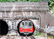
(metro) railways generally have a very small loading gauge. This reduces the cost of tunnel construction. These systems only use their own rolling stock.
History
The loading gauge on the main lines of Great Britain, most of which were built before 1900, is generally smaller than in other countries. In mainland Europe, the slightly larger Berne gaugeBerne gauge
The Berne Gauge or Berne Convention Gauge is an informal but widely-used term for the railway loading gauge considered the standard gauge in continental Europe. The term arises from the international railway conference held and consequent convention signed in Berne, Switzerland in 1912...
(Gabarit passe-partout international, PPI) was agreed in 1912 and came into force in 1914. As a result, British (passenger) trains have smaller loading gauges and smaller interiors, despite being standard gauge
Standard gauge
The standard gauge is a widely-used track gauge . Approximately 60% of the world's existing railway lines are built to this gauge...
along with much of the world.
International Union of Railways (UIC) Gauge
The International Union of RailwaysInternational Union of Railways
The UIC , or International Union of Railways, is an international rail transport industry body.- Brief history :The railways of Europe originated as separate concerns. There were many border changes after World War I and the Treaty of Versailles. Colonial railways were the responsibility of the...
(UIC) has developed a standard series of loading gauges named A, B, B+ and C.
- PPI - the predecessor of the UIC gauges had the maximum dimensions 3.15 by with an almost round roof top.
- UIC A: The smallest (slightly larger than PPI gauge). Maximum dimensions 3.15 by.
- UIC B: Most of the high-speed TGV tracks in France are built to UIC B. Maximum dimensions 3.15 by.
- UIC B+: New structures in France are being built to UIC B+. Up to 4.28 metre it features a width of 2.5 metre to accommodate ISO containers.
- UIC C: The Central European gauge. In Germany and other central European countries the railway systems are built to UIC C gauges, sometimes with an increment in the width to allow for Scandinavian trains to reach German stations directly. Maximum dimensions 3.15 by.
Continental Europe
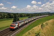
In Continental Europe, the UIC directives were supplanted by ERA Technical Specifications for Interoperability Technical Specifications for Interoperability (TSI) of European Union in 2002 which has defined a number of recommendations to harmonize the train systems. The TSI Rolling Stock (2002/735/EC) has taken over the UIC Gauges definitions defining Kinematic Gauges with a reference profile such that Gauges GA and GB have a height of 4.35 metre (they differ in shape) with Gauge GC rising to 4.7 metre allowing for a width of 3.08 metre of the flat roof. All cars must fall within an envelope of 3.15 metre wide on a 250 metre radius curve. The TGVTGV
The TGV is France's high-speed rail service, currently operated by SNCF Voyages, the long-distance rail branch of SNCF, the French national rail operator....
s, which are 2.9 metre wide, fall within this limit.
The designation of a GB+ loading gauge refers to the plan to create a pan-European freight network for ISO containers and trailers with loaded ISO containers. These container trains (piggy-back trains) fit into the B envelope with a flat top so that only minor changes are required for the widespread structures built to loading gauge B on continental Europe. Currently some structures on the British Isles are extended to fit with GB+ as well, whereas the first lines to be rebuilt start at the channel tunnel
Channel Tunnel
The Channel Tunnel is a undersea rail tunnel linking Folkestone, Kent in the United Kingdom with Coquelles, Pas-de-Calais near Calais in northern France beneath the English Channel at the Strait of Dover. At its lowest point, it is deep...
.
- GA
- GB
- GB1
- GB2
- GB+
- GC
- GI3
Double-decker carriages
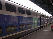
SNCF TGV Duplex
The TGV Duplex is a French high-speed train of the TGV family, operated by SNCF, the French national railway company. It is unique among TGV trains in that it features bi-level carriages. The Duplex inaugurated the third generation of TGV trainsets, and was specially designed to increase capacity...
carriages are 4.32 metres (14.2 ft) high.
Great Britain
Network RailNetwork Rail
Network Rail is the government-created owner and operator of most of the rail infrastructure in Great Britain .; it is not responsible for railway infrastructure in Northern Ireland...
uses a W loading gauge classification system of freight transport ranging from W6A (smallest) through W7, W8, W9, W9Plus, W10, W11 to W12 (largest). The definitions assume a common "lower sector structure gauge" with a common freight platform at 1100 mm above rail.
In addition, C1 provides a specification for coach stock and UK1 for high speed rail. There is also a gauge for locomotives. The size of container that can be conveyed depends both upon the size of the load that can be conveyed and the design of the rolling stock.
- W6a: Available over the majority of the British rail network.
- W8: Allows standard 2.6 metre high shipping containers to be carried on standard wagons.
- W9: Allows 2.9 metre high Hi-Cube shipping containers to be carried on "Megafret" wagons which have lower deck height with reduced capacity. At 2.6 metre wide it allows for 2.5 metre wide Euro shipping containers which are designed to carry Euro-palletPalletA pallet , sometimes called a skid, is a flat transport structure that supports goods in a stable fashion while being lifted by a forklift, pallet jack, front loader or other jacking device. A pallet is the structural foundation of a unit load which allows handling and storage efficiencies...
s efficiently - W10: Allows 2.9 metre high Hi-Cube shipping containers to be carried on standard wagons and also allows 2.5 metre wide Euro shipping containers. Larger than UIC A.
- W11: Little used but larger than UIC B.
- W12: Slightly wider than W10 at 2.6 metre to accommodate refrigerated containers. Recommended clearance for new structures, such as bridges and tunnels.
- UIC GC: Channel TunnelChannel TunnelThe Channel Tunnel is a undersea rail tunnel linking Folkestone, Kent in the United Kingdom with Coquelles, Pas-de-Calais near Calais in northern France beneath the English Channel at the Strait of Dover. At its lowest point, it is deep...
and Channel Tunnel Rail LinkChannel Tunnel Rail LinkHigh Speed 1 , officially known as the Channel Tunnel Rail Link and originally as the Continental Main Line , is a high-speed railway line running from London through Kent to the British end of the Channel Tunnel.The line was built to carry international passenger traffic from the United Kingdom...
to London; with proposals to enable GB+ northwards from London via an upgraded Midland Main LineMidland Main LineThe Midland Main Line is a major railway route in the United Kingdom, part of the British railway system.The present-day line links London St...
.
A strategy was adopted in 2004 to guide enhancements of loading gauges and in 2007 the Network Rail Freight Route Utilisation Strategy
Network Rail Freight Route Utilisation Strategy
The Freight Route Utilisation Strategy is a Route Utilisation Strategy, published by Network Rail in March 2007. It is one of only two which have the perspective of the network as whole. It was included in a map published by the Office of Rail Regulation as established in May 2007...
was published which identified a number of key routes where the loading gauge should be cleared to W10 standard and that where structures are being renewed that W12 is the preferred standard.
Height and width of containers that can be carried on GB gauges (Height by width). Units as per source material.
- W9: 9 in 0 in (2.74 m) by 2.6 metre
- W10: 9 in 6 in (2.9 m) by 2.5 metre
- W11: 9 in 6 in (2.9 m) by 2.55 metre
- W12: 9 in 6 in (2.9 m) by 2.6 metre
Sweden
Sweden uses shapes similar to the Central European loading gauge but trains are wider. There are three main classes in use (width × height):- Class A is 3.4 by (same height as UIC C).
- Class B is 3.4 by (similar height as UIC B).
- Class C is 3.6 by with a completely flat roof top.
While the Bern Gauge width of 3.15 metre is used for 2+2 seats per row the Scandinavian 3.4 metre width allows for 2+3 seats per row. This is used in the Regina X50
Regina (train)
The Regina is a Swedish model of electric multiple unit passenger train, manufactured by Bombardier Transportation . It is used by the national passenger railway SJ along with numerous regional and private operators, in variants designated X50, X51, X52, X53, X54 and X55, and in two- and...
and later models on the Stockholm-Värmland relation. Similarly the newer Chinese high-speed trains use 2+3 seats per row on wider loading gauge tracks. The Swedish width is also allowed on some German railway tracks especially the relation from Berlin to the ferry lines connecting Malmö in Southern Sweden.
Netherlands
In the Netherlands a similar shape to the UIC C is used that rises to 4.7 metre in height. The trains are wider allowing for 3.4 metre width similar to Sweden. Most of the Dutch passenger trains use double-decker railcars for a maximum capacity.Betuweroute and Channel Tunnel
- BetuwerouteBetuwerouteThe Betuweroute is a double track freight railway from Rotterdam to Germany. Betuweroute is the official name, after the Betuwe area through which it passes, but the line is popularly referred to as Betuwelijn, after an older track in the same region. The Germans have named their part the...
: 4.1 by - Channel TunnelChannel TunnelThe Channel Tunnel is a undersea rail tunnel linking Folkestone, Kent in the United Kingdom with Coquelles, Pas-de-Calais near Calais in northern France beneath the English Channel at the Strait of Dover. At its lowest point, it is deep...
: 4.1 by
North America
The American loading gauge for freight cars on the North American rail network is generally based on standards set by the Association of American RailroadsAssociation of American Railroads
The Association of American Railroads is an industry trade group representing primarily the major freight railroads of North America . Amtrak and some regional commuter railroads are also members...
(AAR) (Mechanical Division). The most widespread standards are AAR Plate B and AAR Plate C, but higher loading gauges have been introduced on selected routes to accommodate rolling stock that make better economic use of the network, such as auto carriers and double-stack container loads
Double-stack rail transport
Double-stack rail transport is a form of Intermodal freight transport where intermodal containers are stacked two high on railroad cars. Introduced in North America in 1984, double stack has become increasingly common, being used for nearly 70% of United States intermodal shipments...
.
Listed here are the maximum heights and widths for cars. However, the specification in each plate shows a car cross-section that tapers at the top and bottom, meaning that a compliant car is not permitted to fill an entire rectangle of the maximum height and width.
| Plate | Width | Height | Truck Bogie A bogie is a wheeled wagon or trolley. In mechanics terms, a bogie is a chassis or framework carrying wheels, attached to a vehicle. It can be fixed in place, as on a cargo truck, mounted on a swivel, as on a railway carriage/car or locomotive, or sprung as in the suspension of a caterpillar... centers | Comments | |||
|---|---|---|---|---|---|---|---|
| B | 10 | 3.25 | 15 | 4.62 | 41 | 12.57 | For longer truck centers, the width is decreased according to graph AAR Plate B-1. |
| C | 10 | 3.25 | 15 | 4.72 | with 46 | 14.1 | For longer truck centers, the width is decreased according to graph AAR Plate C-1. |
| D | 10 | 3.25 | 15 | 4.62 | as with Plate B, but the car cross-section is larger at the top and a little larger at the bottom. | ||
| E | 10 | 3.25 | 15 | 4.8 | as with Plate C. | ||
| F | 10 | 3.25 | 17 | 5.18 | as with Plate C. | ||
| H | 20 | 6.15 | e.g. Double Stacks. | ||||
| J | 9 foot | e.g. 89 ft (27.1 m) Long flatcar Flatcar A flatcar is a piece of railroad or railway rolling stock that consists of an open, flat deck on four or six wheels or a pair of trucks or bogies . The deck of the car can be wood or steel, and the sides of the deck can include pockets for stakes or tie-down points to secure loads... s. |
|||||
| K | 10 | 3.25 | 20 | 6.15 | e.g., Autorack Autorack An autorack, also known as an auto carrier, is a specialized piece of railroad rolling stock used to transport automobiles and light trucks, generally from factories to automotive distributors... (road vehicles on trains). |
||

Autorack
An autorack, also known as an auto carrier, is a specialized piece of railroad rolling stock used to transport automobiles and light trucks, generally from factories to automotive distributors...
s, airplane parts cars as well as 20 in 2 in (6.15 m) high double-stacked containers
Intermodal container
An intermodal container is a standardized reusable steel box used for the safe, efficient and secure storage and movement of materials and products within a global containerized intermodal freight transport system...
in container well cars, means that many, but not all, lines are now designed for a higher loading gauge. The width of these extra height cars is covered by Plate C-1.
The standard North American passenger railcar is 10 in 6 in (3.2 m) wide by 14 in 6 in (4.42 m) high and measures 85 in 0 in (25.91 m) over coupler faces with 59 in 6 in (18.14 m) truck
Bogie
A bogie is a wheeled wagon or trolley. In mechanics terms, a bogie is a chassis or framework carrying wheels, attached to a vehicle. It can be fixed in place, as on a cargo truck, mounted on a swivel, as on a railway carriage/car or locomotive, or sprung as in the suspension of a caterpillar...
centers or 86 in 0 in (26.21 m) over coupler faces with 60 in 0 in (18.29 m) truck centers. In the 1940s and 1950s, the American passenger car loading gauge was increased to a 16 in 6 in (5.03 m) height in the West to accommodate dome car
Dome car
A dome car is a type of railway passenger car that has a glass dome on the top of the car where passengers can ride and see in all directions around the train. It also can include features of a coach, lounge car, dining car or observation...
s and later Superliner
Superliner (railcar)
The Superliner is a double decker passenger car used by Amtrak on long haul trains that do not use the Northeast Corridor. The initial cars were built by Pullman-Standard in the late 1970s and a second order was built in the mid 1990s by Bombardier Transportation...
s and other double-decker trains.
New York Subway
The New York City SubwayNew York City Subway
The New York City Subway is a rapid transit system owned by the City of New York and leased to the New York City Transit Authority, a subsidiary agency of the Metropolitan Transportation Authority and also known as MTA New York City Transit...
is an amalgamation of three former constituent companies, and while all are standard gauge
Standard gauge
The standard gauge is a widely-used track gauge . Approximately 60% of the world's existing railway lines are built to this gauge...
, inconsistencies in loading gauge prevent cars from the former BMT and IND
Independent Subway System
The Independent Subway System , formerly known as the Independent City-Owned Subway System or the Independent City-Owned Rapid Transit Railroad, was a rapid transit rail system in New York City that is now part of the New York City Subway...
systems from running on the lines of the former IRT
Interborough Rapid Transit Company
The Interborough Rapid Transit Company was the private operator of the original underground New York City Subway line that opened in 1904, as well as earlier elevated railways and additional rapid transit lines in New York City. The IRT was purchased by the City in June 1940...
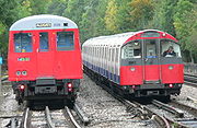
system, and vice versa. This is mainly because IRT tunnels and stations are approximately 1 feet (304.8 mm) narrower than the others, meaning that IRT cars running on the BMT or IND lines would have gaps of over 8 inches (203.2 mm) between the train and some platforms, whereas BMT and IND cars would not even fit into an IRT station without hitting the platform edge. Taking this into account, all maintenance vehicles are built to IRT loading gauge so that they can be operated over the entire network, and employees are responsible for minding the gap.
Another inconsistency is the permissible train car length. Cars in the former IRT system can be as long as 51 feet (15.54 m); cars in the former BMT and IND can be longer: on the Canarsie, Jamaica, and Myrtle Avenue lines the cars are limited to 60 feet (18.29 m), while on the rest of the BMT and IND lines plus the Staten Island Railroad (which uses modified IND stock) the cars may be as long as 75 feet (22.86 m) long.
Japan (Shinkansen)
ShinkansenShinkansen
The , also known as THE BULLET TRAIN, is a network of high-speed railway lines in Japan operated by four Japan Railways Group companies. Starting with the Tōkaidō Shinkansen in 1964, the network has expanded to currently consist of of lines with maximum speeds of , of Mini-shinkansen with a...
network employs standard gauge and maximum width of 3.4 metre and maximum height of 4.5 metre.
Australia
The standard gauge lines of New South Wales Government RailwaysNew South Wales Government Railways
The New South Wales Government Railways was the government department that operated the New South Wales Government's railways until the establishment of the Public Transport Commission in 1972. Although later known officially as the Department of Railways, New South Wales, it was still generally...
(NSWGR) allowed for a width of 9 in 6 in (2.9 m) until 1910, after a conference of the states created a new standard of 10 in 6 in (3.2 m). The narrow widths have mostly been eliminated, except, for example, at the mainline platforms at Gosford railway station and some sidings. The longest carriages are 72' 6".
The Commonwealth Railways
Commonwealth Railways
The Commonwealth Railways were established in 1912, as part of a government department, currently called the Department of Infrastructure, Transport, Regional Development and Local Government, by the Government of Australia to construct the missing link in the east-west transcontinental railway and...
adopted the national standard of 10 in 6 in (3.2 m) when they were established in 1912, although no connection with New South Wales was made until 1970.
The height of the NSW loading gauge just happens to allow for double decker trains in Sydney, while the Victorian loading gauge (in this populous city) is not quite tall enough to allow for double deck trains in Melbourne (except for one experimental train).
An NSW HV Composite Bogie Brake Van of 1884 was 8 foot wide and 11 in 5 in (3.48 m) tall.
A single deck Electric train of the 1920s was 10 in 6 in (3.2 m) wide, with track centres widened to 12 in 0 in (3.66 m) to suit. With metrication in 1973, track centres of new work were widened to 13 foot
A double deck Electric Tangara train of the 2000s was 3000mm wide. Track centres from Penrith railway station
Penrith railway station
Penrith railway station is located on the West Coast Main Line in the United Kingdom. It serves the town of Penrith, Cumbria and is less than one mile from its centre...
to Mount Victoria railway station and Gosford and Wyong have been gradually widened to suit.
Passenger
- The smallest loading gauge for a railway of the gauge track is Delhi MetroDelhi MetroDelhi Metro is a rapid transit system serving Delhi, Gurgaon, Noida and Ghaziabad in the National Capital Region of India. It is one of the largest metro networks in the world. The network consists of six lines with a total length of with 142 stations of which 35 are underground...
. Which is 3250 millimetre wide and 4140 millimetre high. - Indian RailwaysIndian RailwaysIndian Railways , abbreviated as IR , is a departmental undertaking of Government of India, which owns and operates most of India's rail transport. It is overseen by the Ministry of Railways of the Government of India....
(including Pakistan RailwaysPakistan RailwaysThis article is about the rail company in Pakistan. For technical details and operations see: Transport in Pakistan.Pakistan Railways is a national state-owned rail transport service of Pakistan, head-quartered in Lahore. It is administered by the federal government under the Ministry of Railways....
) also gauge track have very large loading gauge. 3660 millimetre wide and 5300 millimetre high for passenger traffic. - The Russian (including Finnish and ex-Soviet) loading gauges are also very large. Same loading gauge as the Indian (including Pakistan), 3660 millimetre wide and 5300 millimetre high for passenger traffic, on the gauge track compare the gauge track.
Freight
- In India and Pakistan, 3250 millimetre wide and 7150 millimetre high on the freight only lines, and 3250 millimetre wide and 6150 millimetre high on the passenger lines.
- In Finland, Russia and Kazakhstan, 3250 millimetre wide and 6150 millimetre high.
Narrow gauge
Narrow gauge railways generally have smaller a loading gauge than standard gauge ones, and this is a major reason for cost savings rather than the railgauge itself. For example, the Lyn locomotiveLyn locomotive
Lyn was a 2-4-2 tank steam locomotive built by the Baldwin Locomotive Works in 1898 for the Lynton and Barnstaple Railway. After construction in Philadelphia, the loco was broken down, crated to Barnstaple, and reassembled by L&B staff in their Pilton workshops.Lyn, like all the locomotives on...
of the Lynton and Barnstaple Railway
Lynton and Barnstaple Railway
The Lynton & Barnstaple Railway opened as an independent railway in May 1898. It was a single track narrow gauge railway slightly over long running through the rugged and picturesque area bordering Exmoor in North Devon, England. Although opened after the 1896 Light Railways Act came into force,...
is 7 in 2 in (2.18 m) wide. By comparison, several standard gauge 73 class locomotives
New South Wales 73 class locomotive
The New South Wales 73 class are a diesel-hydraulic locomotive originally purchased and operated by the New South Wales Government Railways of Australia, and now operated by a variety of private operators. The NSWGR were in the need of powerful diesel shunting locomotives in the 1960s. They had...
of the NSWR
New South Wales Government Railways
The New South Wales Government Railways was the government department that operated the New South Wales Government's railways until the establishment of the Public Transport Commission in 1972. Although later known officially as the Department of Railways, New South Wales, it was still generally...
, which are 9 in 3 in (2.82 m) wide, have been converted for use on cane tramways, where there are no narrow bridges, tunnels or track centres to cause trouble. The 6E1
South African Class 6E1, Series 9
In 1981 and 1982 the South African Railways placed eighty-five Class 6E1, Series 9 electric locomotives with a Bo-Bo wheel arrangement in main line service.-Manufacturer:...
locomotive of the South African Railways are 9 in 6 in (2.9 m) wide.
A large numbers of railways using the gauge used the same rolling stock plans which were 7 in 0 in (2.13 m) wide.
Japan
Japanese national network operated by Japan Railways Group employs narrow gauge and has maximum width of 3000 millimetre and maximum height of 4100 millimetre; however, a number JR lines were constructed as private railways prior to nationalisation in the early 20th century, and feature loading gauges smaller than the standard. These include the Chūō Main LineChuo Main Line
The , commonly called the Chūō Line, is one of the major trunk railway lines in Japan. It runs between Tokyo and Nagoya, although it is the slowest direct railway connection between the two cities; the coastal Tōkaidō Main Line is slightly faster, while the Tōkaidō Shinkansen is the fastest rail...
west of Takao
Takao Station
Takao Station is the name of two train stations in Japan:* Takao Station * Takao Station...
, the Minobu Line, and the Yosan Main Line west of Kan'onji
Kan'onji Station
is a railway station on the Yosan Line of Shikoku Railway Company located in Kan'onji, Kagawa, Japan.The station opened on December 20, 1913.- References :...
(3900 millimetre height). Nevertheless, advances in pantograph
Pantograph (rail)
A pantograph for rail lines is a hinged electric-rod device that collects electric current from overhead lines for electric trains or trams. The pantograph typically connects to a one-wire line, with the track acting as the ground wire...
technology have largely eliminated the need for separate rolling stock in these areas.
There are many private railway companies in Japan and the loading gauge is different for each company.
New Zealand
NZR uses gauge.- width brakevan mirrors 8' 7.75"
- width brakevan 7' 0.125"
- height brakevan 11' 2"
South Africa
South African national network employs gauge and has maximum width of 3048 mm (10 ft) and maximum height of 3962 mm (13 ft).Festiniog Railway
- gauge
- width (brakevan mirrors) 6' 10"
- width (brakevan body) 6' 0"
- height 5' 7.5"
Narrow gauge lines of the Victorian RailwaysNarrow gauge lines of the Victorian RailwaysThe former Victorian Railways, the state railway authority in Victoria, Australia built a number of experimental narrow gauge railway lines around the beginning of the 20th century. Although all were closed by the early 1960s, parts of two have been reopened as heritage railways.- Background :A...
- gauge
- minimun radius 132'
- width 7' 0" see Everard CalthropEverard CalthropEverard Richard Calthrop was a British railway engineer and inventor. Calthrop was a notable promoter and builder of narrow gauge railways, especially of gauge, and was especially prominent in India. His most notable achievement was the Barsi Light Railway; however he is best known in his home...
Structure gauge
The structure gaugeStructure gauge
The structure gauge, also called the minimum clearance outline, is the minimum height and width of tunnels and bridges as well as the minimum height and width of the doors that allow a rail siding access into a warehouse...
, which is the lowest and narrowest bridge or tunnel complements the loading gauge which is the tallest and widest vehicle. There is a gap between the two and some allowance needs to be made for the dynamic movement of the vehicles.
External links
- EU Directive 2002/732/EC - High Speed Rail Rolling Stock Standards
- Berne and all that (1992 diagram of European loading gauges) at crowsnest.com (Diagrams do not show)
- AAR "plate" loading gauge diagrams compared to UIC (pdf & Autocad)
- Railway Loading Gauges at Joyce's World of Transport Eclectica
- Loading Gauges at The Self Site
- UIC Leaflets
- Railway industrial Clearance Association
- British Track Gauge & Loading Gauge