
JTAG
Encyclopedia
Joint Test Action Group (JTAG) is the common name for what was later standardized as the IEEE
1149.1 Standard Test Access Port and Boundary-Scan Architecture. It was initially devised for testing printed circuit board
s using boundary scan
and is still widely used for this application.
Today JTAG is also widely used for IC
debug port
s. In the embedded processor market, essentially all modern processors support JTAG when they have enough pins. Embedded system
s development relies on debugger
s talking to chips with JTAG to perform operations like single stepping and breakpoint
ing. Digital electronics products such as cell phones
or a wireless access point
generally have no other debug or test interfaces.
s were becoming standard and connections were being made between ICs which were not available to probes. The majority of manufacturing and field faults in circuit boards were due to solder
joints on the boards, imperfections in board connections, or the bonds and bond wires from IC pads to pin lead frames. JTAG was meant to provide a pins-out view from one IC pad to another so all these faults could be discovered.
The industry standard finally became an IEEE standard in 1990 as IEEE Std. 1149.1-1990 after many years of initial use. That same year Intel released the first processor
with JTAG: the 80486 which led to quicker industry adoption by all manufacturers. In 1994, a supplement that contains a description of the boundary scan description language
(BSDL) was added. Further refinements regarding the use of all-zeros for EXTEST, separating the use of SAMPLE from PRELOAD and better support for OBSERVE_ONLY cells were made and released in 2001. Since 1990, this standard has been adopted by electronics
companies all over the world. Boundary-scan is now mostly synonymous with JTAG, but JTAG has essential uses beyond such manufacturing applications.
s, making it an essential mechanism for debugging
embedded system
s which may not support any other debug-capable communications channel. On most systems, JTAG-based debugging is available from the very first instruction after CPU reset, letting it support development of early boot software which runs before anything is set up. A so-called in-circuit emulator
(or more correctly, "JTAG adapter") uses JTAG as the transport mechanism to access on-chip debug modules inside the target CPU
. Those modules let software developers debug the software of an embedded system
directly at the machine instruction level when needed, or (more typically) in terms of high level language source code
Debug support is for many software developers the main reason to be interested in JTAG. There are entire debugging architectures built up using JTAG, such as ARM CoreSight and Nexus (plus vendor-specific ones that may not be documented except under NDA
) helping move JTAG-centric debugging environments away from early processor-specific designs. Processors can normally be halted, single stepped, or let run freely. Code breakpoints are supported, both for code in RAM (often using a special machine instruction) and in ROM/flash. Data breakpoints are often available, as is bulk data download to RAM. Most designs support “halt mode debugging”, but some allow debuggers to access registers and data busses without needing to halt the core being debugged. Some toolchains can use ARM Embedded Trace Macrocell (ETM) modules to trigger debugger (or tracing) activity on complex hardware events, like a logic analyser programmed to ignore the first seven accesses to a register from one particular subroutine
Sometimes FPGA developers also use JTAG to develop debugging tools. The same JTAG techniques used to debug software running inside a CPU can help debug other digital design blocks inside an FPGA. For example, custom JTAG instructions can be provided to support reading registers built from arbitrary sets of signals inside the FPGA, providing visibility for behaviors which are invisible to boundary scan operations. Similarly, writing such registers could provide controllability which is not otherwise available.
to transfer data into internal non-volatile device memory (e.g. CPLDs). Some device programmers serve a double purpose for programming as well as debugging the device. In the case of FPGAs, volatile memory devices can also be programmed via the JTAG port normally during development work. In addition, newer parts, for instance Xilinx
Virtex-5, have internal monitoring capability (temperature, voltage and current) accessible via the JTAG port.
JTAG programmers are also used to write software and data into flash memory
. This is usually done using data bus access like the CPU would use, and is sometimes actually handled by a CPU, but in other cases memory chips have JTAG interfaces themselves. Some modern debug architectures, like ARM CoreSight and Nexus, provide internal and external bus master access without needing to halt and take over a CPU. In the worst case, it is usually possible to drive external bus signals using boundary scan support.
As a practical matter, when developing an embedded system, emulating the instruction store is the fastest way to close the edit-compile-test cycle loop. This is because the in-circuit emulator simulating an instruction store can be updated very quickly from the development host, via USB, say. Using e.g. a serial UART port and bootloader to upload firmware makes this edit-compile-test cycle quite slow. Installing firmware via JTAG is intermediate between these extremes, as well as in cost of hardware tools.
can be tested.
In both cases (external and internal), this testing is done with the IC after it is mounted on the circuit card and possibly while in a functioning system. When combined with built-in self-test (BIST
), the JTAG scan chain enables a low overhead, embedded solution to testing an IC for certain static faults (shorts, opens, and logic errors). The scan chain mechanism does not generally help diagnose or test for timing
, temperature or other dynamic operational errors that may occur. Test case
s are often provided in standardized formats such as SVF
, or its binary sibling XSVF, and used in production tests. The ability to perform such testing on finished boards is an essential part of Design For Test
in today's products, increasing the number of faults that can be found before products ship to customers.
together if specific conditions are met, and a test probe
need only connect to a single "JTAG port" to have access to all chips on a circuit board. The connector pins are
Test reset signal is not shown in the image.
 Since only one data line is available, the protocol is serial
. The clock input is at the TCK pin. Clocking changes on TMS steps through a standardized JTAG state machine. The JTAG state machine can reset, access an instruction register, or access data selected by the instruction register.
One bit of data is transferred in and out per TCK clock pulse at the TDI and TDO pins, respectively. Different instructions can be loaded. Instructions for typical ICs might read the chip ID, sample input pins, drive (or float) output pins, manipulate chip functions, or bypass (pipe TDI to TDO to logically shorten chains of multiple chips). The operating frequency of TCK varies depending on all chips in the chain (lowest speed must be used), but it is typically 10-100 MHz (100-10 ns per bit).
The TRST pin is an optional active-low reset to the test logic - usually asynchronous, but sometimes synchronous, depending on the chip. If the pin is not available, the test logic can be reset by switching to the reset state synchronously, using TCK and TMS. Note that resetting test logic doesn't necessarily imply resetting anything else. There are generally some processor-specific JTAG operations which can reset all or part of the chip being debugged.
As with any clocked signal, data presented to TDI must be valid for some chip-specific Setup time before and Hold time after the relevant (here, rising) clock edge. TDO data is valid for some chip-specific time after the falling edge of TCK. In short, there are some constraints on signal timings.
TCK frequencies vary based on chip, board, and adapter capabilities and state. One chip might support a 40 MHz JTAG clock, but only if it's using a 200 MHz clock for non-JTAG operations; and it might need to use a much slower clock when it's in a low power mode. Accordingly, some JTAG adapters support adaptive clocking using an RTCK (Return TCK) signal. Faster TCK frequencies are most useful when JTAG is used to transfer lots of data, such as when storing a system image into NAND flash.
JTAG platforms often add additional signals to the handful defined by the IEEE 1149.1 specification. A System Reset (SRST) signal is quite common, letting debuggers reset the whole system not just the parts with JTAG support. Sometimes there are event signals used to trigger activity by the host or by the device being monitored through JTAG; or additional control lines.
Even though few consumer products provide an explicit JTAG port connector, the connections are often available on the printed circuit board
as a remnant from development prototyping
and/or production. When exploited, these connections often provide the most viable means for reverse engineering
.
To use JTAG, a host is connected to the target's JTAG signals (TMS, TCK, TDI, TDO, etc.) through some kind of JTAG adapter, which may need to handle issues like level shifting and galvanic isolation. The adapter connects to the host using some interface such as USB, PCI, Ethernet, and so forth.
So at a basic level, using JTAG involves reading and writing instructions and their associated data registers; and sometimes involves running a number of test cycles. Behind those registers is hardware that is not specified by JTAG, and which has its own states that will be affected by JTAG activities.
Most JTAG hosts use the shortest path between two states, perhaps constrained by quirks of the adapter. (For example, one adapter only handles paths whose lengths are multiples of seven bits.) Some layers built on top of JTAG monitor the state transitions, and use uncommon paths to trigger higher level operations. Some ARM cores use such sequences to enter and exit a two-wire (non-JTAG) SWD mode. A Zero Bit Scan (ZBS) sequence is used in IEEE 1149.7 to access advanced functionality such as switching TAPs into and out of scan chains, power management, and a different two-wire mode.
On exit from the RESET state, the instruction register is preloaded with either BYPASS or IDCODE. This allows JTAG hosts to identify the size and, at least partially, contents of the scan chain to which they are connected. (They can enter the RESET state then scan the Data Register until they read back the data they wrote. A BYPASS register has only a zero bit; while an IDCODE register is 32-bits and starts with a one. So the bits not written by the host can easily be mapped to TAPs.) Such identification is often used to sanity check manual configuration, since IDCODE is often unspecific. It could for example identify an ARM Cortex-M3 based microcontroller, without specifying the microcontroller vendor or model; or a particular FPGA, but not how it has been programmed.
A common idiom involves shifting BYPASS into the instruction registers of all TAPs except one, which receives some other instruction. That way all TAPs except one expose a single bit data register, and values can be selectively shifted into or out of that one TAP's data register without affecting any other TAP.
The IEEE 1149.1 (JTAG) standard describes a number of instructions to support boundary scan applications. Some of these instructions are "mandatory", but TAPs used for debug instead of boundary scan testing sometimes provide minimal or no support for these instructions. Those "mandatory" instructions operate on the Boundary Scan Register (BSR) defined in the BSDL
file, and include:
IEEE-defined "Optional" instructions include:
Devices may define more instructions, and those definitions should be part of a BSDL file provided by the manufacturer. They will often just be marked as PRIVATE.
contain a shift-register cell for each signal pin of the device. These registers are connected in a dedicated path around the device's boundary (hence the name). The path creates a virtual access capability that circumvents the normal inputs and outputs, providing direct control of the device and detailed visibility for signals.
The contents of the boundary scan register, including signal I/O capabilities, are usually described by the manufacturer using a part-specific BSDL
file. These are used with design 'netlists' from CAD/EDA systems to develop tests used in board manufacturing. Commercial test systems will often cost several thousand dollars for a fully-fledged system, and include diagnostic options to accurately pin-point faults such as open circuits and shorts. They may also offer schematic or layout viewers to depict the fault in a graphical manner.
To provide the boundary scan capability, IC vendors add additional logic to each of their devices, including scan cells for each of the signal pins. These cells are then connected together to form the boundary scan shift register (BSR), which is connected to a TAP controller. These designs are parts of most Verilog or VHDL libraries. Overhead for this additional logic is minimal, and generally is well worth the price to enable efficient testing at the board level.
processor, the ARM1136 core. The processor itself has extensive JTAG capability, similar to what is found in other CPU cores, and it's integrated into chips with even more extensive capabilities accessed through JTAG.
So this is a non-trivial example, which is representative of a significant cross section of JTAG-enabled systems. In addition, it shows how control mechanisms are built using JTAG's register read/write primitives, and how those combine to facilitate testing and debugging complex logic elements; CPUs are common, but FPGAs and ASIC
s include other complex elements which need to be debugged.
Licensees of this core integrate it into chips, usually combining it with other TAPs as well as numerous peripherals and memory. (Peripherals and memory comprise the bulk of SoC
designs; ARM cores don't take up much chip area.) One of those other TAPs will handle boundary scan testing for the whole chip; it is not supported by the debug tap. Examples of such chips include:
Those processors are both intended for use in wireless handsets such as cell phones, which is part of the reason they include TAP controllers which modify the JTAG scan chain: debugging low power operation requires accessing chips when they are largely powered off, and thus when not all TAPs are operational. That scan chain modification functionality is one subject of a forthcoming IEEE 1149.7 standard.
, where a software tool (the "debugger") uses JTAG to communicate with a system being debugged:
That model resembles the model used in other ARM cores. Non-ARM systems generally have similar capabilities, perhaps implemented using the Nexus protocols on top of JTAG, or other vendor-specific schemes.
Older ARM7 and ARM9 cores include an EmbeddedICE module which combines most of those facilities, but has an awkward mechanism for instruction execution: the debugger must drive the CPU instruction pipeline, clock by clock, and directly access the data buses to read and write data to the CPU. The ARM11 uses the same model for trace support (ETM, ETB) as those older cores.
Newer ARM cores, such as the Cortex-A8, closely resemble this debug model, but build on a Debug Access Port (DAP) instead of direct CPU access. They are also decoupled from JTAG so they can be hosted over ARM's two-wire "SWD" interface instead of just the six-wire JTAG interface. (ARM takes the four standard JTAG signals and adds the optional TRST, plus the RTCK signal used for adaptive clocking.) Also, the newer cores have updated trace support.
So for example a JTAG host might HALT the core, entering Debug Mode, and then read CPU registers using ITR and DCC. After saving processor state, it could write those registers with whatever values it needs, then execute arbitrary algorithms on the CPU, accessing memory and peripherals to help characterize the system state. After the debugger performs those operations, the state may be restored and execution continued using the RESTART instruction.
Debug mode is also entered asynchronously by the debug module triggering a watchpoint or breakpoint, or by issuing a BKPT (breakpoint) instruction from the software being debugged. When it is not being used for instruction tracing, the ETM can also trigger entry to debug mode; it supports complex triggers sensitive to state and history, as well as the simple address comparisons exposed by the debug module. Asynchronous transitions to debug mode are detected by polling the DSCR register. This is how single stepping is implemented: HALT the core, set a temporary breakpoint at the next instruction or next high-level statement, RESTART, poll DSCR until you detect asynchronous entry to debug state, remove that temporary breakpoint, repeat.
ARM processors support an alternative debug mode, called Monitor Mode, to work with such situations. (This is distinct from the Secure Monitor Mode implemented as part of security extensions on newer ARM cores; it manages debug operations, not security transitions.) In those cases, breakpoints and watchpoints trigger a special kind of hardware exception, transferring control to a "debug monitor" running as part of the system software. This monitor will communicate with the debugger using the DCC, and could arrange for example to single step only a single process while other processes (and interrupt handlers) continue running.
Freescale has COP and OnCE (On-Chip Emulation). OnCE includes a JTAG command which makes a TAP enter a special mode where the IR holds OnCE debugging commands for operations such as single stepping, breakpointing, and accessing registers or memory. It also defines EOnCE (Enhanced On-Chip Emulation) presented as addressing real time concerns.
ARM
has an extensive processor core debug architecture (CoreSight) that started with EmbeddedICE (a debug facility available on most ARM cores), and now includes many additional components such as an ETM (Embedded Trace Macrocell), with a high speed trace port, supporting multi-core and multithread tracing. Note that tracing is non-invasive; systems do not need to stop operating to be traced. (However, trace data is too voluminous to use JTAG as more than a trace control channel.)
Nexus defines a processor debug infrastructure which is largely vendor-independent. One of its hardware interfaces is JTAG. It also defines a high speed auxiliary port interface, used for tracing and more. Nexus is used with some newer platforms, such as the Atmel
AVR32 and Freescale MPC5500 series processors.
If you want to acquire a JTAG adapter, you first need to decide what systems it must support. Everything else follows from that, including your software options. Low-end adapters may cost less than $US 50 and have limited hardware and software support. High-end adapters can cost a hundred times as much, including software support, and have corresponding improvements in capability.
 There are no official standards for JTAG adapter physical connectors. Development boards usually include a header to support preferred development tools; in some cases they include multiple such headers, because they need to support multiple such tools. For example, a microcontroller, FPGA, and ARM application processor will rarely share tools, so a development board using all of those components might have three or more headers. Production boards may omit the headers; or when space is tight, just provide JTAG signal access using test points.
Some common pinouts for 2.54mm (0.1 inch) pin headers are:
Those connectors tend to include more than just the four standardized signals (TMS, TCK, TDI, TDO). Usually reset signals are provided, one or both of TRST (TAP reset) and SRST (system reset). The connector usually provides the board-under-test's logic supply voltage so that the JTAG adapter's will use the appropriate logic levels. The board voltage may also serve as a "board present" debugger input. Other event input or output signals may be provided, or general purpose I/O (GPIO) lines, to support more complex debugging architectures.
Higher end products frequently use dense connectors (frequently 38-pin MICTOR
connectors) to support high-speed tracing
in conjunction with JTAG operations. A recent trend is to have development boards integrate a USB interface to JTAG, where a second channel is used for a serial port. (Smaller boards can also be powered through USB. Since modern PCs tend to omit serial ports, such integrated debug links can significantly reduce clutter for developers.) Production boards often rely on bed-of-nails connections to test points for testing and programming.
). A separate power supply may be needed. There are both "dumb" adapters, where the host decides and performs all JTAG operations; and "smart" ones, where some of that work is performed inside the adapter, often driven by a microcontroller. The "smart" adapters eliminate link latencies for operation sequences that may involve polling for status changes between steps, and may accordingly offer faster throughput.
At this writing (mid-2009) adapters with full speed USB links are probably the most common approach, and new products often include high speed USB support. Higher end products often support Ethernet, with the advantage that the debug host can be quite remote. Adapters which support high speed trace ports generally include several megabytes of trace buffer and provide high speed links (USB or Ethernet) to get that data to the host.
Personal computer parallel port
adapters are simple and inexpensive, but they are relatively slow because they use the host CPU to change each bit ("bit banging"). They have declined in usefulness because newer computers do not have parallel port hardware. Driver support is also a problem, because the adapter electronics varied so widely.
Serial port adapters also exist, and are similarly declining in usefulness. They generally involve either slower bitbanging than a parallel port, or a microcontroller translating some command protocol to JTAG operations. Such serial adapters are also not fast, but their command protocols could generally be reused on top of higher speed links.
With all JTAG adapters, software support is a basic concern. Many vendors do not publish the protocols used by their JTAG adapter hardware, limiting their customers to the tool chains supported by those vendors. This is a particular issue for "smart" adapters, some of which embed significant amounts of knowledge about how to interact with specific CPUs.
All such software tends to include basic debugger support: stopping, halting, single stepping, breakpoints, data structure browsing, and so on.
Commercial tools tend to provide tools like very accurate simulators and trace analysis, which are not currently available as open source.
from STMicroelectronics
.
Institute of Electrical and Electronics Engineers
The Institute of Electrical and Electronics Engineers is a non-profit professional association headquartered in New York City that is dedicated to advancing technological innovation and excellence...
1149.1 Standard Test Access Port and Boundary-Scan Architecture. It was initially devised for testing printed circuit board
Printed circuit board
A printed circuit board, or PCB, is used to mechanically support and electrically connect electronic components using conductive pathways, tracks or signal traces etched from copper sheets laminated onto a non-conductive substrate. It is also referred to as printed wiring board or etched wiring...
s using boundary scan
Boundary scan
Boundary scan is a method for testing interconnects on printed circuit boards or sub-blocks inside an integrated circuit. Boundary scan is also widely used as a debugging method to watch integrated circuit pin states, measure voltage, or analyze sub-blocks inside an integrated circuit.The Joint...
and is still widely used for this application.
Today JTAG is also widely used for IC
Integrated circuit
An integrated circuit or monolithic integrated circuit is an electronic circuit manufactured by the patterned diffusion of trace elements into the surface of a thin substrate of semiconductor material...
debug port
Debug port
Debug port is a port included in a device to simplify development and debugging, which is not necessary for normal functioning of it. Debug ports are usually not removed or disabled to avoid costs of design changes, and can be used by modders and hackers to get extra functionality.Examples:*...
s. In the embedded processor market, essentially all modern processors support JTAG when they have enough pins. Embedded system
Embedded system
An embedded system is a computer system designed for specific control functions within a larger system. often with real-time computing constraints. It is embedded as part of a complete device often including hardware and mechanical parts. By contrast, a general-purpose computer, such as a personal...
s development relies on debugger
Debugger
A debugger or debugging tool is a computer program that is used to test and debug other programs . The code to be examined might alternatively be running on an instruction set simulator , a technique that allows great power in its ability to halt when specific conditions are encountered but which...
s talking to chips with JTAG to perform operations like single stepping and breakpoint
Breakpoint
In software development, a breakpoint is an intentional stopping or pausing place in a program, put in place for debugging purposes. It is also sometimes simply referred to as a pause....
ing. Digital electronics products such as cell phones
Mobile phone
A mobile phone is a device which can make and receive telephone calls over a radio link whilst moving around a wide geographic area. It does so by connecting to a cellular network provided by a mobile network operator...
or a wireless access point
Wireless access point
In computer networking, a wireless access point is a device that allows wireless devices to connect to a wired network using Wi-Fi, Bluetooth or related standards...
generally have no other debug or test interfaces.
Overview
JTAG was an industry group formed in 1985 to develop a method to test populated circuit boards after manufacture. At the time, multi-layer boards and non-lead-frame ICIntegrated circuit
An integrated circuit or monolithic integrated circuit is an electronic circuit manufactured by the patterned diffusion of trace elements into the surface of a thin substrate of semiconductor material...
s were becoming standard and connections were being made between ICs which were not available to probes. The majority of manufacturing and field faults in circuit boards were due to solder
Solder
Solder is a fusible metal alloy used to join together metal workpieces and having a melting point below that of the workpiece.Soft solder is what is most often thought of when solder or soldering are mentioned and it typically has a melting range of . It is commonly used in electronics and...
joints on the boards, imperfections in board connections, or the bonds and bond wires from IC pads to pin lead frames. JTAG was meant to provide a pins-out view from one IC pad to another so all these faults could be discovered.
The industry standard finally became an IEEE standard in 1990 as IEEE Std. 1149.1-1990 after many years of initial use. That same year Intel released the first processor
Central processing unit
The central processing unit is the portion of a computer system that carries out the instructions of a computer program, to perform the basic arithmetical, logical, and input/output operations of the system. The CPU plays a role somewhat analogous to the brain in the computer. The term has been in...
with JTAG: the 80486 which led to quicker industry adoption by all manufacturers. In 1994, a supplement that contains a description of the boundary scan description language
Boundary scan description language
Boundary scan description language is a description language for electronics testing using JTAG. It has been added to the IEEE Std. 1149.1, and BSDL files are increasingly well supported by JTAG tools for boundary scan applications, and by test case generators.- BSDL Overview :BSDL is a VHDL subset...
(BSDL) was added. Further refinements regarding the use of all-zeros for EXTEST, separating the use of SAMPLE from PRELOAD and better support for OBSERVE_ONLY cells were made and released in 2001. Since 1990, this standard has been adopted by electronics
Electronics
Electronics is the branch of science, engineering and technology that deals with electrical circuits involving active electrical components such as vacuum tubes, transistors, diodes and integrated circuits, and associated passive interconnection technologies...
companies all over the world. Boundary-scan is now mostly synonymous with JTAG, but JTAG has essential uses beyond such manufacturing applications.
Debugging
Although it was originally designed for testing printed circuit board assemblies, today JTAG is also used for accessing sub-blocks of integrated circuitIntegrated circuit
An integrated circuit or monolithic integrated circuit is an electronic circuit manufactured by the patterned diffusion of trace elements into the surface of a thin substrate of semiconductor material...
s, making it an essential mechanism for debugging
Debugging
Debugging is a methodical process of finding and reducing the number of bugs, or defects, in a computer program or a piece of electronic hardware, thus making it behave as expected. Debugging tends to be harder when various subsystems are tightly coupled, as changes in one may cause bugs to emerge...
embedded system
Embedded system
An embedded system is a computer system designed for specific control functions within a larger system. often with real-time computing constraints. It is embedded as part of a complete device often including hardware and mechanical parts. By contrast, a general-purpose computer, such as a personal...
s which may not support any other debug-capable communications channel. On most systems, JTAG-based debugging is available from the very first instruction after CPU reset, letting it support development of early boot software which runs before anything is set up. A so-called in-circuit emulator
In-circuit emulator
An in-circuit emulator is a hardware device used to debug the software of an embedded system. It was historically in the form of bond-out processor which has many internal signals brought out for the purpose of debugging...
(or more correctly, "JTAG adapter") uses JTAG as the transport mechanism to access on-chip debug modules inside the target CPU
Central processing unit
The central processing unit is the portion of a computer system that carries out the instructions of a computer program, to perform the basic arithmetical, logical, and input/output operations of the system. The CPU plays a role somewhat analogous to the brain in the computer. The term has been in...
. Those modules let software developers debug the software of an embedded system
Embedded system
An embedded system is a computer system designed for specific control functions within a larger system. often with real-time computing constraints. It is embedded as part of a complete device often including hardware and mechanical parts. By contrast, a general-purpose computer, such as a personal...
directly at the machine instruction level when needed, or (more typically) in terms of high level language source code
Debug support is for many software developers the main reason to be interested in JTAG. There are entire debugging architectures built up using JTAG, such as ARM CoreSight and Nexus (plus vendor-specific ones that may not be documented except under NDA
Non-disclosure agreement
A non-disclosure agreement , also known as a confidentiality agreement , confidential disclosure agreement , proprietary information agreement , or secrecy agreement, is a legal contract between at least two parties that outlines confidential material, knowledge, or information that the parties...
) helping move JTAG-centric debugging environments away from early processor-specific designs. Processors can normally be halted, single stepped, or let run freely. Code breakpoints are supported, both for code in RAM (often using a special machine instruction) and in ROM/flash. Data breakpoints are often available, as is bulk data download to RAM. Most designs support “halt mode debugging”, but some allow debuggers to access registers and data busses without needing to halt the core being debugged. Some toolchains can use ARM Embedded Trace Macrocell (ETM) modules to trigger debugger (or tracing) activity on complex hardware events, like a logic analyser programmed to ignore the first seven accesses to a register from one particular subroutine
Sometimes FPGA developers also use JTAG to develop debugging tools. The same JTAG techniques used to debug software running inside a CPU can help debug other digital design blocks inside an FPGA. For example, custom JTAG instructions can be provided to support reading registers built from arbitrary sets of signals inside the FPGA, providing visibility for behaviors which are invisible to boundary scan operations. Similarly, writing such registers could provide controllability which is not otherwise available.
Storing firmware
Besides debugging, another application of JTAG is allowing device programmer hardwareProgrammer (hardware)
In field of computer hardware, the term programmer, chip programmer or device programmer refers to a hardware device that configures programmable non-volatile circuits such as EPROMs, EEPROMs, Flashs, PALs, FPGAs or programmable logic circuits....
to transfer data into internal non-volatile device memory (e.g. CPLDs). Some device programmers serve a double purpose for programming as well as debugging the device. In the case of FPGAs, volatile memory devices can also be programmed via the JTAG port normally during development work. In addition, newer parts, for instance Xilinx
Xilinx
Xilinx, Inc. is a supplier of programmable logic devices. It is known for inventing the field programmable gate array and as the first semiconductor company with a fabless manufacturing model....
Virtex-5, have internal monitoring capability (temperature, voltage and current) accessible via the JTAG port.
JTAG programmers are also used to write software and data into flash memory
Flash memory
Flash memory is a non-volatile computer storage chip that can be electrically erased and reprogrammed. It was developed from EEPROM and must be erased in fairly large blocks before these can be rewritten with new data...
. This is usually done using data bus access like the CPU would use, and is sometimes actually handled by a CPU, but in other cases memory chips have JTAG interfaces themselves. Some modern debug architectures, like ARM CoreSight and Nexus, provide internal and external bus master access without needing to halt and take over a CPU. In the worst case, it is usually possible to drive external bus signals using boundary scan support.
As a practical matter, when developing an embedded system, emulating the instruction store is the fastest way to close the edit-compile-test cycle loop. This is because the in-circuit emulator simulating an instruction store can be updated very quickly from the development host, via USB, say. Using e.g. a serial UART port and bootloader to upload firmware makes this edit-compile-test cycle quite slow. Installing firmware via JTAG is intermediate between these extremes, as well as in cost of hardware tools.
Boundary scan testing
In many ICs today, all the pins that connect to electronic logic are linked together in a set called the Boundary Scan chain. By using JTAG to manipulate the chip's external interface (inputs and outputs to other chips) it is possible to test for certain faults, caused perhaps by bad soldering. By using JTAG to manipulate its internal interface (to on-chip registers), the combinational logicCombinational logic
In digital circuit theory, combinational logic is a type of digital logic which is implemented by boolean circuits, where the output is a pure function of the present input only. This is in contrast to sequential logic, in which the output depends not only on the present input but also on the...
can be tested.
In both cases (external and internal), this testing is done with the IC after it is mounted on the circuit card and possibly while in a functioning system. When combined with built-in self-test (BIST
Built-in self-test
A built-in self-test or built-in test is a mechanism that permits a machine to test itself. Engineers design BISTs to meet requirements such as:*high reliability*lower repair cycle timesor constraints such as:...
), the JTAG scan chain enables a low overhead, embedded solution to testing an IC for certain static faults (shorts, opens, and logic errors). The scan chain mechanism does not generally help diagnose or test for timing
Timing
Timing is the time when something happens or the spacing of events in time. Some typical uses are:* The act of measuring the elapsed time of something or someone, often at athletic events such as swimming or running, where participants are timed with a device such as a stopwatch...
, temperature or other dynamic operational errors that may occur. Test case
Test case
A test case in software engineering is a set of conditions or variables under which a tester will determine whether an application or software system is working correctly or not. The mechanism for determining whether a software program or system has passed or failed such a test is known as a test...
s are often provided in standardized formats such as SVF
Serial Vector Format
Serial Vector Format is a vector exchange format, designed to enable transfer of boundary scan vectors between tools. SVF is expressing test patterns that represent the stimulus, expected response, and mask data for IEEE 1149.1-based tests. The standard was jointly developed by companies Texas...
, or its binary sibling XSVF, and used in production tests. The ability to perform such testing on finished boards is an essential part of Design For Test
Design For Test
Design for Test is a name for design techniques that add certain testability features to a microelectronic hardware product design. The premise of the added features is that they make it easier to develop and apply manufacturing tests for the designed hardware...
in today's products, increasing the number of faults that can be found before products ship to customers.
Electrical characteristics
A JTAG interface is a special four/five-pin interface added to a chip, designed so that multiple chips on a board can have their JTAG lines daisy-chainedDaisy chain (electrical engineering)
In electrical and electronic engineering a daisy chain is a wiring scheme in which multiple devices are wired together in sequence or in a ring...
together if specific conditions are met, and a test probe
Test probe
A test probe is a physical device used to connect electronic test equipment to the device under test . They range from very simple, rugged devices to complex probes that are sophisticated, expensive, and fragile.- Voltage probes :Voltage probes are intended to measure voltages on the DUT...
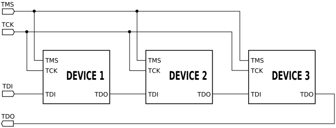
need only connect to a single "JTAG port" to have access to all chips on a circuit board. The connector pins are
- TDI (Test Data In)
- TDO (Test Data Out)
- TCK (Test Clock)
- TMS (Test Mode Select)
- TRST (Test Reset) optional.
Test reset signal is not shown in the image.
Serial communications
In telecommunication and computer science, serial communication is the process of sending data one bit at a time, sequentially, over a communication channel or computer bus. This is in contrast to parallel communication, where several bits are sent as a whole, on a link with several parallel channels...
. The clock input is at the TCK pin. Clocking changes on TMS steps through a standardized JTAG state machine. The JTAG state machine can reset, access an instruction register, or access data selected by the instruction register.
One bit of data is transferred in and out per TCK clock pulse at the TDI and TDO pins, respectively. Different instructions can be loaded. Instructions for typical ICs might read the chip ID, sample input pins, drive (or float) output pins, manipulate chip functions, or bypass (pipe TDI to TDO to logically shorten chains of multiple chips). The operating frequency of TCK varies depending on all chips in the chain (lowest speed must be used), but it is typically 10-100 MHz (100-10 ns per bit).
The TRST pin is an optional active-low reset to the test logic - usually asynchronous, but sometimes synchronous, depending on the chip. If the pin is not available, the test logic can be reset by switching to the reset state synchronously, using TCK and TMS. Note that resetting test logic doesn't necessarily imply resetting anything else. There are generally some processor-specific JTAG operations which can reset all or part of the chip being debugged.
As with any clocked signal, data presented to TDI must be valid for some chip-specific Setup time before and Hold time after the relevant (here, rising) clock edge. TDO data is valid for some chip-specific time after the falling edge of TCK. In short, there are some constraints on signal timings.
TCK frequencies vary based on chip, board, and adapter capabilities and state. One chip might support a 40 MHz JTAG clock, but only if it's using a 200 MHz clock for non-JTAG operations; and it might need to use a much slower clock when it's in a low power mode. Accordingly, some JTAG adapters support adaptive clocking using an RTCK (Return TCK) signal. Faster TCK frequencies are most useful when JTAG is used to transfer lots of data, such as when storing a system image into NAND flash.
JTAG platforms often add additional signals to the handful defined by the IEEE 1149.1 specification. A System Reset (SRST) signal is quite common, letting debuggers reset the whole system not just the parts with JTAG support. Sometimes there are event signals used to trigger activity by the host or by the device being monitored through JTAG; or additional control lines.
Even though few consumer products provide an explicit JTAG port connector, the connections are often available on the printed circuit board
Printed circuit board
A printed circuit board, or PCB, is used to mechanically support and electrically connect electronic components using conductive pathways, tracks or signal traces etched from copper sheets laminated onto a non-conductive substrate. It is also referred to as printed wiring board or etched wiring...
as a remnant from development prototyping
Prototype
A prototype is an early sample or model built to test a concept or process or to act as a thing to be replicated or learned from.The word prototype derives from the Greek πρωτότυπον , "primitive form", neutral of πρωτότυπος , "original, primitive", from πρῶτος , "first" and τύπος ,...
and/or production. When exploited, these connections often provide the most viable means for reverse engineering
Reverse engineering
Reverse engineering is the process of discovering the technological principles of a device, object, or system through analysis of its structure, function, and operation...
.
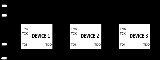
Communications model
In JTAG, devices expose one or more test access ports (TAPs). The picture above shows three TAPs, which might be individual chips or might be modules inside one chip. A daisy chain of TAPs is called a scan chain, or (loosely) a target. Scan chains can be arbitrarily long, but in practice twenty TAPs is unusually long.To use JTAG, a host is connected to the target's JTAG signals (TMS, TCK, TDI, TDO, etc.) through some kind of JTAG adapter, which may need to handle issues like level shifting and galvanic isolation. The adapter connects to the host using some interface such as USB, PCI, Ethernet, and so forth.
Primitives
The host communicates with the TAPs by manipulating TMS and TDI in conjunction with TCK, then reading results through TDO (which is the only standard host-side input). TMS/TDI/TCK output transitions create the basic JTAG communication primitive on which higher layer protocols build:- State switching ... All TAPs are in the same state, and that state changes on TCK transitions. This JTAG state machine is part of the JTAG spec, and includes sixteen states. There are six “stable states” where keeping TMS stable prevents the state from changing. In all other states, TCK always changes that state. In addition, asserting TRST forces entry to one of those stable states (Test_Logic_Reset), in a slightly quicker way than the alternative of holding TMS high and cycling TCK five times.
- Shifting ... Most parts of the JTAG state machine support two stable states used to transfer data. Each TAP has an instruction register (IR) and a data register (DR). The size of those registers varies between TAPs, and those registers are combined through TDI and TDO to form a large shift register. (The size of the DR is a function of the value in that TAP's current IR, and possibly of the value specified by a SCAN_N instruction.) There are three operations defined on that shift register:
- Capturing a temporary value ... entry to the Shift_IR stable state goes via the Capture_IR state, loading the shift register with a partially fixed value (not the current instruction). Entry to the Shift_DR stable state goes via the Capture_DR state, loading the value of the Data Register specified by the TAP's current IR.
- Shifting that value bit-by-bit, in either the Shift_IR or Shift_DR stable state; TCK transitions will shift the shift register one bit, from TDI towards TDO, exactly like a SPISerial Peripheral Interface BusThe Serial Peripheral Interface Bus or SPI bus is a synchronous serial data link standard named by Motorola that operates in full duplex mode. Devices communicate in master/slave mode where the master device initiates the data frame. Multiple slave devices are allowed with individual slave select ...
mode 1 data transfer through a daisy chain of devices (with TMS=0 acting like the chip select signal, TDI as MOSI, etc.). - Updating IR or DR from the temporary value shifted in, on transition through the Update_IR or Update_DR state. Note that it is not possible to read (capture) a register without writing (updating) it, and vice versa. A common idiom adds flag bits to say whether the update should have side effects, or whether the hardware is ready to execute such side effects.
- Running ... One stable state is called Run_Test/Idle. The distinction is TAP-specific. Clocking TCK in the Idle state has no particular side effects, but clocking it in the Run_Test state may change system state. For example, some ARM9 cores support a debugging mode where TCK cycles in the Run_Test state drive the instruction pipeline.
So at a basic level, using JTAG involves reading and writing instructions and their associated data registers; and sometimes involves running a number of test cycles. Behind those registers is hardware that is not specified by JTAG, and which has its own states that will be affected by JTAG activities.
Most JTAG hosts use the shortest path between two states, perhaps constrained by quirks of the adapter. (For example, one adapter only handles paths whose lengths are multiples of seven bits.) Some layers built on top of JTAG monitor the state transitions, and use uncommon paths to trigger higher level operations. Some ARM cores use such sequences to enter and exit a two-wire (non-JTAG) SWD mode. A Zero Bit Scan (ZBS) sequence is used in IEEE 1149.7 to access advanced functionality such as switching TAPs into and out of scan chains, power management, and a different two-wire mode.
JTAG IEEE Std 1149.1 (boundary scan) instructions
Instruction register sizes tend to be small, perhaps four or seven bits wide. Except for BYPASS and EXTEST, all instruction opcodes are defined by the TAP implementor, as are their associated data registers; undefined instruction codes should not be used. Two key instructions are:- The BYPASS instruction, opcode all ones regardless of the TAP's instruction register size, must be supported by all TAPs. It is associated with a single bit data register (also called BYPASS) which always reads as zero.
- The optional IDCODE instruction, with an implementor-defined opcode. IDCODE is associated with a 32-bit register (IDCODE). Its data uses a standardized format that includes a manufacturer code (derived from the JEDECJEDECThe JEDEC Solid State Technology Association, formerly known as the Joint Electron Devices Engineering Council , is an independent semiconductor engineering trade organization and standardization body...
Standard Manufacturer's Identification Code standard, JEP-106), a part number assigned by the manufacturer, and a part version code. IDCODE is widely, but not universally, supported.
On exit from the RESET state, the instruction register is preloaded with either BYPASS or IDCODE. This allows JTAG hosts to identify the size and, at least partially, contents of the scan chain to which they are connected. (They can enter the RESET state then scan the Data Register until they read back the data they wrote. A BYPASS register has only a zero bit; while an IDCODE register is 32-bits and starts with a one. So the bits not written by the host can easily be mapped to TAPs.) Such identification is often used to sanity check manual configuration, since IDCODE is often unspecific. It could for example identify an ARM Cortex-M3 based microcontroller, without specifying the microcontroller vendor or model; or a particular FPGA, but not how it has been programmed.
A common idiom involves shifting BYPASS into the instruction registers of all TAPs except one, which receives some other instruction. That way all TAPs except one expose a single bit data register, and values can be selectively shifted into or out of that one TAP's data register without affecting any other TAP.
The IEEE 1149.1 (JTAG) standard describes a number of instructions to support boundary scan applications. Some of these instructions are "mandatory", but TAPs used for debug instead of boundary scan testing sometimes provide minimal or no support for these instructions. Those "mandatory" instructions operate on the Boundary Scan Register (BSR) defined in the BSDL
Boundary scan description language
Boundary scan description language is a description language for electronics testing using JTAG. It has been added to the IEEE Std. 1149.1, and BSDL files are increasingly well supported by JTAG tools for boundary scan applications, and by test case generators.- BSDL Overview :BSDL is a VHDL subset...
file, and include:
- EXTEST for external testing, such as using pins to probe board-level behaviors
- PRELOAD loading pin output values before EXTEST (sometimes combined with SAMPLE)
- SAMPLE reading pin values into the boundary scan register
IEEE-defined "Optional" instructions include:
- CLAMP a variant of BYPASS which drives the output pins using the PRELOADed values
- HIGHZ deactivates the outputs of all pins
- INTEST for internal testing, such as using pins to probe on-chip behaviors
- RUNBIST places the chip in a self-test mode
- SCAN_N configures a scan path select register (SCREG) affecting the signals to which other boundary scan operations apply
- USERCODE returns a user-defined code, for example to identify which FPGA image is active
Devices may define more instructions, and those definitions should be part of a BSDL file provided by the manufacturer. They will often just be marked as PRIVATE.
Boundary scan register
Devices communicate to the world via a set of input and output pins. By themselves, these pins provide limited visibility into the workings of the device. However, devices that support boundary scanBoundary scan
Boundary scan is a method for testing interconnects on printed circuit boards or sub-blocks inside an integrated circuit. Boundary scan is also widely used as a debugging method to watch integrated circuit pin states, measure voltage, or analyze sub-blocks inside an integrated circuit.The Joint...
contain a shift-register cell for each signal pin of the device. These registers are connected in a dedicated path around the device's boundary (hence the name). The path creates a virtual access capability that circumvents the normal inputs and outputs, providing direct control of the device and detailed visibility for signals.
The contents of the boundary scan register, including signal I/O capabilities, are usually described by the manufacturer using a part-specific BSDL
Boundary scan description language
Boundary scan description language is a description language for electronics testing using JTAG. It has been added to the IEEE Std. 1149.1, and BSDL files are increasingly well supported by JTAG tools for boundary scan applications, and by test case generators.- BSDL Overview :BSDL is a VHDL subset...
file. These are used with design 'netlists' from CAD/EDA systems to develop tests used in board manufacturing. Commercial test systems will often cost several thousand dollars for a fully-fledged system, and include diagnostic options to accurately pin-point faults such as open circuits and shorts. They may also offer schematic or layout viewers to depict the fault in a graphical manner.
To provide the boundary scan capability, IC vendors add additional logic to each of their devices, including scan cells for each of the signal pins. These cells are then connected together to form the boundary scan shift register (BSR), which is connected to a TAP controller. These designs are parts of most Verilog or VHDL libraries. Overhead for this additional logic is minimal, and generally is well worth the price to enable efficient testing at the board level.
Example: ARM11 debug TAP
A concrete example will help show the way JTAG works in real systems. The example here is the debug tap of an ARM11ARM11
ARM11 is an ARM architecture 32-bit RISC microprocessor family which introduced the ARMv6 architectural additions. These include SIMD media instructions, multiprocessor support and a new cache architecture...
processor, the ARM1136 core. The processor itself has extensive JTAG capability, similar to what is found in other CPU cores, and it's integrated into chips with even more extensive capabilities accessed through JTAG.
So this is a non-trivial example, which is representative of a significant cross section of JTAG-enabled systems. In addition, it shows how control mechanisms are built using JTAG's register read/write primitives, and how those combine to facilitate testing and debugging complex logic elements; CPUs are common, but FPGAs and ASIC
ASIC
ASIC may refer to:* Application-specific integrated circuit, an integrated circuit developed for a particular use, as opposed to a customised general-purpose device.* ASIC programming language, a dialect of BASIC...
s include other complex elements which need to be debugged.
Licensees of this core integrate it into chips, usually combining it with other TAPs as well as numerous peripherals and memory. (Peripherals and memory comprise the bulk of SoC
System-on-a-chip
A system on a chip or system on chip is an integrated circuit that integrates all components of a computer or other electronic system into a single chip. It may contain digital, analog, mixed-signal, and often radio-frequency functions—all on a single chip substrate...
designs; ARM cores don't take up much chip area.) One of those other TAPs will handle boundary scan testing for the whole chip; it is not supported by the debug tap. Examples of such chips include:
- The OMAP2420 includes a boundary scan TAP, the ARM1136 Debug TAP, an ETB11 trace buffer tap, a C55x DSPTexas Instruments TMS320Texas Instruments TMS320 is a blanket name for a series of digital signal processors from Texas Instruments. It was introduced on April 8, 1983 through the TMS32010 processor, which was then the fastest DSP on the market....
, and a tap for an ARM7TDMI-based imaging engine, with the boundary scan TAP ("ICEpick-B") having the ability to splice TAPs into and out of the JTAG scan chain. - The i.MX31I.MX31The Freescale i.MX31 is an application processor, consisting of anARM1136JF-S processor core with some additional peripherals. It is part of Freescale's i.MX range of ARM9/11-based multimedia application processor family. It is intended for use in low-power applications needing high performance...
processor is similar, although its "System JTAG" boundary scan TAP is very different from ICEpick, and it includes a TAP for its DMA engine instead of a DSP and imaging engine.
Those processors are both intended for use in wireless handsets such as cell phones, which is part of the reason they include TAP controllers which modify the JTAG scan chain: debugging low power operation requires accessing chips when they are largely powered off, and thus when not all TAPs are operational. That scan chain modification functionality is one subject of a forthcoming IEEE 1149.7 standard.
JTAG facilities
This debug tap exposes several standard instructions, and a few specifically designed for hardware-assisted debuggingDebugging
Debugging is a methodical process of finding and reducing the number of bugs, or defects, in a computer program or a piece of electronic hardware, thus making it behave as expected. Debugging tends to be harder when various subsystems are tightly coupled, as changes in one may cause bugs to emerge...
, where a software tool (the "debugger") uses JTAG to communicate with a system being debugged:
- BYPASS, IDCODE ... standard instructions as described above
- EXTEST, INTEST ... standard instructions, but operating on the core instead of an external boundary scan chain. EXTEST is nominally for writing data to the core, INTEST is nominally for reading it; but two scan chains are exceptions to that rule.
- SCAN_N ... ARM instruction to select the numbered scan chain used with EXTEST or INTEST. There are six scan chains:
- 0 ... Device ID Register, 40 bits of read-only identification data
- 1 ... Debug Status and Control Register (DSCR), 32 bits used to operate the debug facilities
- 4 ... Instruction Transfer Register (ITR), 33 bits (32 instruction plus one status bit) used to execute processor instructions while in a special "Debug Mode" (see below)
- 5 ... Debug Communications Channel (DCC), 34 bits (one long data word plus two status bits) used for bidirectional data transfer to the core. This is used both in debug mode, and possibly at runtime when talking to debugger-aware software.
- 6 ... Embedded Trace Module (ETM), 40 bits (7 bit address, one 32-bit long data word, and a R/W bit) used to control the operation of a passive instruction and data trace mechanism. This feeds either an on-chip Embedded Trace Buffer (ETB), or an external high speed trace data collection pod. Tracing supports passive debugging (examining execution history) and profiling for performance tuning.
- 7 ... debug module, 40 bits (7 bit address, one 32-bit long data word, and a R/W bit) used to access hardware breakpoints, watchpoints, and more. These can be written while the processor is running; it does not need to be in Debug Mode.
- HALT, RESTART ... ARM11-specific instructions to halt and restart the CPU. Halting it puts the core into the "Debug Mode", where the ITR can be used to execute instructions, including using the DCC to transfer data between the debug (JTAG) host and the CPU.
- ITRSEL ... ARM11-specific instruction to accelerate some operations with ITR.
That model resembles the model used in other ARM cores. Non-ARM systems generally have similar capabilities, perhaps implemented using the Nexus protocols on top of JTAG, or other vendor-specific schemes.
Older ARM7 and ARM9 cores include an EmbeddedICE module which combines most of those facilities, but has an awkward mechanism for instruction execution: the debugger must drive the CPU instruction pipeline, clock by clock, and directly access the data buses to read and write data to the CPU. The ARM11 uses the same model for trace support (ETM, ETB) as those older cores.
Newer ARM cores, such as the Cortex-A8, closely resemble this debug model, but build on a Debug Access Port (DAP) instead of direct CPU access. They are also decoupled from JTAG so they can be hosted over ARM's two-wire "SWD" interface instead of just the six-wire JTAG interface. (ARM takes the four standard JTAG signals and adds the optional TRST, plus the RTCK signal used for adaptive clocking.) Also, the newer cores have updated trace support.
Halt mode debugging
One basic way to debug software is to present a single threaded model, where the debugger periodically stops execution of the program and examines its state as exposed by register contents and memory (including peripheral controller registers). When interesting program events approach, a person may want to single step instructions (or lines of source code) to watch how a particular misbehavior happens.So for example a JTAG host might HALT the core, entering Debug Mode, and then read CPU registers using ITR and DCC. After saving processor state, it could write those registers with whatever values it needs, then execute arbitrary algorithms on the CPU, accessing memory and peripherals to help characterize the system state. After the debugger performs those operations, the state may be restored and execution continued using the RESTART instruction.
Debug mode is also entered asynchronously by the debug module triggering a watchpoint or breakpoint, or by issuing a BKPT (breakpoint) instruction from the software being debugged. When it is not being used for instruction tracing, the ETM can also trigger entry to debug mode; it supports complex triggers sensitive to state and history, as well as the simple address comparisons exposed by the debug module. Asynchronous transitions to debug mode are detected by polling the DSCR register. This is how single stepping is implemented: HALT the core, set a temporary breakpoint at the next instruction or next high-level statement, RESTART, poll DSCR until you detect asynchronous entry to debug state, remove that temporary breakpoint, repeat.
Monitor mode debugging
Modern software is often too complex to work well with such a single threaded model. For example, a processor used to control a motor (perhaps one driving a saw blade) may not be able to safely enter halt mode ... it may need to continue handling interrupts to ensure physical safety of people and/or machinery. Issuing a HALT instruction using JTAG might be dangerous.ARM processors support an alternative debug mode, called Monitor Mode, to work with such situations. (This is distinct from the Secure Monitor Mode implemented as part of security extensions on newer ARM cores; it manages debug operations, not security transitions.) In those cases, breakpoints and watchpoints trigger a special kind of hardware exception, transferring control to a "debug monitor" running as part of the system software. This monitor will communicate with the debugger using the DCC, and could arrange for example to single step only a single process while other processes (and interrupt handlers) continue running.
Common extensions
Microprocessor vendors have often defined their own core-specific debugging extensions. Such vendors include Infineon, MIPS with EJTAG, and more. If the vendor does not adopt a standard (such as the ones used by ARM processors; or Nexus), they need to define their own solution. If they support boundary scan, they generally build debugging over JTAG.Freescale has COP and OnCE (On-Chip Emulation). OnCE includes a JTAG command which makes a TAP enter a special mode where the IR holds OnCE debugging commands for operations such as single stepping, breakpointing, and accessing registers or memory. It also defines EOnCE (Enhanced On-Chip Emulation) presented as addressing real time concerns.
ARM
ARM architecture
ARM is a 32-bit reduced instruction set computer instruction set architecture developed by ARM Holdings. It was named the Advanced RISC Machine, and before that, the Acorn RISC Machine. The ARM architecture is the most widely used 32-bit ISA in numbers produced...
has an extensive processor core debug architecture (CoreSight) that started with EmbeddedICE (a debug facility available on most ARM cores), and now includes many additional components such as an ETM (Embedded Trace Macrocell), with a high speed trace port, supporting multi-core and multithread tracing. Note that tracing is non-invasive; systems do not need to stop operating to be traced. (However, trace data is too voluminous to use JTAG as more than a trace control channel.)
Nexus defines a processor debug infrastructure which is largely vendor-independent. One of its hardware interfaces is JTAG. It also defines a high speed auxiliary port interface, used for tracing and more. Nexus is used with some newer platforms, such as the Atmel
Atmel
Atmel Corporation is a manufacturer of semiconductors, founded in 1984. Its focus is on system-level solutions built around flash microcontrollers...
AVR32 and Freescale MPC5500 series processors.
Widespread uses
- Except for some of the very lowest end systems, essentially all embedded systems platforms have a JTAG port to support in-circuit debugging and firmware programming as well as for boundary scan testing:
- ARM ArchitectureARM architectureARM is a 32-bit reduced instruction set computer instruction set architecture developed by ARM Holdings. It was named the Advanced RISC Machine, and before that, the Acorn RISC Machine. The ARM architecture is the most widely used 32-bit ISA in numbers produced...
processors come with JTAG support, sometimes supporting a two-wire "SWD" variant or high speed tracing of traffic on instruction or data busses. (This alone means most 32-bit processors in the world support JTAG.) - Modern 8-bit and 16-bit MicrocontrollerMicrocontrollerA microcontroller is a small computer on a single integrated circuit containing a processor core, memory, and programmable input/output peripherals. Program memory in the form of NOR flash or OTP ROM is also often included on chip, as well as a typically small amount of RAM...
chips, such as Atmel AVRAtmel AVRThe AVR is a modified Harvard architecture 8-bit RISC single chip microcontroller which was developed by Atmel in 1996. The AVR was one of the first microcontroller families to use on-chip flash memory for program storage, as opposed to one-time programmable ROM, EPROM, or EEPROM used by other...
and TI MSP430TI MSP430The MSP430 is a mixed-signal microcontroller family from Texas Instruments. Built around a 16-bit CPU, the MSP430 is designed for low cost, and specifically, low power consumption embedded applications. The architecture dates from the 1990s and is reminiscent of the DEC PDP-11.-Applications:The...
chips, support JTAG programming and debugging. However, the very smallest chips may not have enough pins to spare (and thus tend to rely on proprietary single-wire programming interfaces); if the pin count is over 32, there is probably a JTAG option. - Almost all FPGAs and CPLDCPLDA complex programmable logic device is a programmable logic device with complexity between that of PALs and FPGAs, and architectural features of both. The building block of a CPLD is the macrocell, which contains logic implementing disjunctive normal form expressions and more specialized logic...
s used today can be programmed via a JTAG port. - Many MIPSMIPS architectureMIPS is a reduced instruction set computer instruction set architecture developed by MIPS Technologies . The early MIPS architectures were 32-bit, and later versions were 64-bit...
and PowerPCPowerPCPowerPC is a RISC architecture created by the 1991 Apple–IBM–Motorola alliance, known as AIM...
processors have JTAG support too
- ARM Architecture
- The PCIPeripheral Component InterconnectConventional PCI is a computer bus for attaching hardware devices in a computer...
bus connector standard contains optional JTAG signals on pins 1-5; PCI-Express contains JTAG signals on pins 5-9. A special JTAG card can be used to reflash a corrupt BIOSBIOSIn IBM PC compatible computers, the basic input/output system , also known as the System BIOS or ROM BIOS , is a de facto standard defining a firmware interface....
. - Boundary scan testing and in-system (device) programming applications are sometimes programmed using the Serial Vector FormatSerial Vector FormatSerial Vector Format is a vector exchange format, designed to enable transfer of boundary scan vectors between tools. SVF is expressing test patterns that represent the stimulus, expected response, and mask data for IEEE 1149.1-based tests. The standard was jointly developed by companies Texas...
, a textual representation of JTAG operations using a simple syntax. Other programming formats include 'JAM' and STAPL plus more recently the IEEE Std. 1532 defined format 'ISC' (short for In-System Configuration). ISC format is used in conjunction with enhanced BSDL models for programmable logic devices (i.e. FPGAs and CPLDs) that include addition ISC_instructions in addition to the basic bare minimum IEEE 1149.1 instructions. FPGA programming tools from Xilinx XilinxXilinx, Inc. is a supplier of programmable logic devices. It is known for inventing the field programmable gate array and as the first semiconductor company with a fabless manufacturing model....
, Altera, Lattice, Cypress, Actel etc.. and will typically be able to export such files. - As mentioned, many boards include JTAG connectors, or just pads, to support manufacturing operations, where boundary scan testing helps verify board quality (identifying bad solder joints, etc.) and to initialize flash memoryFlash memoryFlash memory is a non-volatile computer storage chip that can be electrically erased and reprogrammed. It was developed from EEPROM and must be erased in fairly large blocks before these can be rewritten with new data...
or FPGAs. - JTAG can also support field updates and troubleshooting.
- Primarily of historical interest: Intel's PentiumPentiumThe original Pentium microprocessor was introduced on March 22, 1993. Its microarchitecture, deemed P5, was Intel's fifth-generation and first superscalar x86 microarchitecture. As a direct extension of the 80486 architecture, it included dual integer pipelines, a faster FPU, wider data bus,...
processors supported a "probe mode" supporting JTAG access for debuggers. For a long time, its documentation was withdrawn by Intel. Current x86 processors appear to use JTAG only for boundary scan.
Client support
The target's JTAG interface is accessed using some JTAG-enabled application and some JTAG adapter hardware. There is a wide range of such hardware, optimized for purposes such as production testing, debugging high speed systems, low cost microcontroller development, and so on. In the same way, the software used to drive such hardware can be quite varied. Software developers mostly use JTAG for debugging and updating firmware.If you want to acquire a JTAG adapter, you first need to decide what systems it must support. Everything else follows from that, including your software options. Low-end adapters may cost less than $US 50 and have limited hardware and software support. High-end adapters can cost a hundred times as much, including software support, and have corresponding improvements in capability.
JTAG connectors
Some common pinouts for 2.54mm (0.1 inch) pin headers are:
- ARM 2x10 pin (or sometimes the older 2x7), used by almost all ARM based systems
- MIPS EJTAG (2x7 pin) used for MIPSMIPS TechnologiesMIPS Technologies, Inc. , formerly MIPS Computer Systems, Inc., is most widely known for developing the MIPS architecture and a series of pioneering RISC chips. MIPS provides processor architectures and cores for digital home, networking and mobile applications.MIPS Computer Systems Inc. was...
based systems - 2x5 pin AlteraAlteraAltera Corporation is a Silicon Valley manufacturer of PLDs . The company offered its first programmable logic device in 1984. PLDs can be reprogrammed during the design cycle as well as in the field to perform multiple functions, and they support a fairly fast design process...
ByteBlaster-compatible JTAG extended by many vendors - 2x5 pin AVRAVRAVR may refer to:* Avon Valley Railway, a heritage railway in the United Kingdom* Atmel AVR, a family of microcontrollers* Assiniboine Valley Railway, a minimum gauge railway in Winnipeg, Canada...
extends Altera JTAG with SRST (and in some cases TRST and an event output) - 2x7 pin Texas InstrumentsTexas InstrumentsTexas Instruments Inc. , widely known as TI, is an American company based in Dallas, Texas, United States, which develops and commercializes semiconductor and computer technology...
used with DSPsTexas Instruments TMS320Texas Instruments TMS320 is a blanket name for a series of digital signal processors from Texas Instruments. It was introduced on April 8, 1983 through the TMS32010 processor, which was then the fastest DSP on the market....
and ARM-based products such as OMAPOMAPOMAP developed by Texas Instruments is a category of proprietary system on chips for portable and mobile multimedia applications. OMAP devices generally include a general-purpose ARM architecture processor core plus one or more specialized co-processors... - 8 pin (single row) generic PLD JTAG compatible with many Lattice ispDOWNLOAD cables
Those connectors tend to include more than just the four standardized signals (TMS, TCK, TDI, TDO). Usually reset signals are provided, one or both of TRST (TAP reset) and SRST (system reset). The connector usually provides the board-under-test's logic supply voltage so that the JTAG adapter's will use the appropriate logic levels. The board voltage may also serve as a "board present" debugger input. Other event input or output signals may be provided, or general purpose I/O (GPIO) lines, to support more complex debugging architectures.
Higher end products frequently use dense connectors (frequently 38-pin MICTOR
MICTOR
MICTOR is an acronym for Matched Impedance ConnecTOR. It is a connector for printed circuit boards. It can be used for probing boards.-External links:* http://fr.mouser.com/search/Refine.aspx?Ntt=AMP%20MICTOR%20Connectors...
connectors) to support high-speed tracing
Tracing (software)
In software engineering, tracing is a specialized use of logging to record information about a program's execution. This information is typically used by programmers for debugging purposes, and additionally, depending on the type and detail of information contained in a trace log, by experienced...
in conjunction with JTAG operations. A recent trend is to have development boards integrate a USB interface to JTAG, where a second channel is used for a serial port. (Smaller boards can also be powered through USB. Since modern PCs tend to omit serial ports, such integrated debug links can significantly reduce clutter for developers.) Production boards often rely on bed-of-nails connections to test points for testing and programming.
JTAG adapter hardware
Adapter hardware varies widely. When not integrated into a development board, it involves a short cable to attach to a JTAG connector on the target board; a connection to the debugging host, such as a USB, PCI, or Ethernet link; and enough electronics to adapt the two communications domains (and sometimes provide galvanic isolationGalvanic isolation
Galvanic isolation is a principle of isolating functional sections of electrical systems, thus preventing the movement of charge-carrying particles from one section to another, i.e. no direct current flows between the sections. Energy or information can still be exchanged between the sections by...
). A separate power supply may be needed. There are both "dumb" adapters, where the host decides and performs all JTAG operations; and "smart" ones, where some of that work is performed inside the adapter, often driven by a microcontroller. The "smart" adapters eliminate link latencies for operation sequences that may involve polling for status changes between steps, and may accordingly offer faster throughput.
At this writing (mid-2009) adapters with full speed USB links are probably the most common approach, and new products often include high speed USB support. Higher end products often support Ethernet, with the advantage that the debug host can be quite remote. Adapters which support high speed trace ports generally include several megabytes of trace buffer and provide high speed links (USB or Ethernet) to get that data to the host.
Personal computer parallel port
Parallel port
A parallel port is a type of interface found on computers for connecting various peripherals. In computing, a parallel port is a parallel communication physical interface. It is also known as a printer port or Centronics port...
adapters are simple and inexpensive, but they are relatively slow because they use the host CPU to change each bit ("bit banging"). They have declined in usefulness because newer computers do not have parallel port hardware. Driver support is also a problem, because the adapter electronics varied so widely.
Serial port adapters also exist, and are similarly declining in usefulness. They generally involve either slower bitbanging than a parallel port, or a microcontroller translating some command protocol to JTAG operations. Such serial adapters are also not fast, but their command protocols could generally be reused on top of higher speed links.
With all JTAG adapters, software support is a basic concern. Many vendors do not publish the protocols used by their JTAG adapter hardware, limiting their customers to the tool chains supported by those vendors. This is a particular issue for "smart" adapters, some of which embed significant amounts of knowledge about how to interact with specific CPUs.
JTAG for software development
Most development environments for embedded software include JTAG support. There are, broadly speaking, three sources of such software:- Chip Vendors may provide the tools, usually requiring a JTAG adapter they supply. Examples include FPGA vendors such as XilinxXilinxXilinx, Inc. is a supplier of programmable logic devices. It is known for inventing the field programmable gate array and as the first semiconductor company with a fabless manufacturing model....
and AlteraAlteraAltera Corporation is a Silicon Valley manufacturer of PLDs . The company offered its first programmable logic device in 1984. PLDs can be reprogrammed during the design cycle as well as in the field to perform multiple functions, and they support a fairly fast design process...
, AtmelAtmelAtmel Corporation is a manufacturer of semiconductors, founded in 1984. Its focus is on system-level solutions built around flash microcontrollers...
for its AVR8 and AVR32 product lines, and Texas InstrumentsTexas InstrumentsTexas Instruments Inc. , widely known as TI, is an American company based in Dallas, Texas, United States, which develops and commercializes semiconductor and computer technology...
for most of its DSP and micro products. Such tools tend to be highly featured, and may be the only real option for highly specialized chips like FPGAs and DSPs. Lower end software tools may be provided free of charge. The JTAG adapters themselves are not free, although sometimes they are bundled with development boards. - Tool Vendors may supply them, usually in conjunction with multiple chip vendors to provide cross-platform development support. ARMARM architectureARM is a 32-bit reduced instruction set computer instruction set architecture developed by ARM Holdings. It was named the Advanced RISC Machine, and before that, the Acorn RISC Machine. The ARM architecture is the most widely used 32-bit ISA in numbers produced...
-based products have a particularly rich third party market, and a number of those vendors have expanded to non-ARM platforms like MIPSMIPS architectureMIPS is a reduced instruction set computer instruction set architecture developed by MIPS Technologies . The early MIPS architectures were 32-bit, and later versions were 64-bit...
and PowerPCPowerPCPowerPC is a RISC architecture created by the 1991 Apple–IBM–Motorola alliance, known as AIM...
. Tool vendors sometimes build products around free software like GCCGNU Compiler CollectionThe GNU Compiler Collection is a compiler system produced by the GNU Project supporting various programming languages. GCC is a key component of the GNU toolchain...
and GDBGNU DebuggerThe GNU Debugger, usually called just GDB and named gdb as an executable file, is the standard debugger for the GNU software system. It is a portable debugger that runs on many Unix-like systems and works for many programming languages, including Ada, C, C++, Objective-C, Free Pascal, Fortran, Java...
, with GUI support frequently using EclipseEclipse (software)Eclipse is a multi-language software development environment comprising an integrated development environment and an extensible plug-in system...
. JTAG adapters are sometimes sold along with support bundles. - Open Source tools exist. As noted above, GCC and GDB form the core of a good toolchain, and there are GUI environments to support them.
All such software tends to include basic debugger support: stopping, halting, single stepping, breakpoints, data structure browsing, and so on.
Commercial tools tend to provide tools like very accurate simulators and trace analysis, which are not currently available as open source.
Serial wire debug
Serial Wire Debug (SWD) is an 2-pin electrical alternative JTAG interface with the same JTAG protocol on top. Uses the existing GND connection. SWD uses an ARM CPU standard bi-directional wire protocol, defined in the ARM Debug Interface v5. This enables the debugger to become another AMBA bus master for access to system memory and peripheral or debug registers. Performance of . Has built in error detection. On JTAG devices with SWD capability the TMS and TCK are used as SWDIO and SWCLK signals, allowing for dual-mode programmers. An example of microcontrollers with SWD interface are the STM32STM32
STM32 is a family of multiple series of microcontroller ICs, by STMicroelectronics , based on the 32-bit RISC Cortex-M3 and Cortex-M4F cores from ARM Holdings...
from STMicroelectronics
STMicroelectronics
STMicroelectronics is an Italian-French electronics and semiconductor manufacturer headquartered in Geneva, Switzerland.While STMicroelectronics corporate headquarters and the headquarters for EMEA region are based in Geneva, the holding company, STMicroelectronics N.V. is registered in Amsterdam,...
.
See also
- AOI Automated optical inspectionAutomated optical inspectionAutomated optical inspection is an automated visual inspection of a wide range of products, such as printed circuit boards , LCDs, transistors, automotive parts, lids and labels on product packages or agricultural products...
- AXI Automated x-ray inspectionAutomated x-ray inspectionAutomated inspection is a technology based on the same principles as automated optical inspection . It uses as its source, instead of visible light, to automatically inspect features, which are typically hidden from view....
- ICT In-circuit testIn-circuit testIn-circuit test is an example of white box testing where an electrical probe tests a populated printed circuit board , checking for shorts, opens, resistance, capacitance, and other basic quantities which will show whether the assembly was correctly fabricated...
- Functional testing (see Acceptance testing)
- Nexus 5001
- Non-JTAG hardware debug interfaces:
- Background Debug Mode interfaceBackground Debug Mode interfaceBackground Debug Mode interface is an electronic interface that allows debugging of embedded systems. Specifically, it provides in-circuit debugging functionality in microcontrollers...
- Spy-Bi-WireSpy-Bi-WireSpy-Bi-Wire is a serialised JTAG protocol developed by Texas Instruments for their MSP430 micro controllers.In this protocol only two connections are used instead of the usual four pins for the general JTAG interface. The two connections are a bidirectional data output, and a clock...
- DebugWire on Atmel AVRAtmel AVRThe AVR is a modified Harvard architecture 8-bit RISC single chip microcontroller which was developed by Atmel in 1996. The AVR was one of the first microcontroller families to use on-chip flash memory for program storage, as opposed to one-time programmable ROM, EPROM, or EEPROM used by other...
- Background Debug Mode interface
- Open JTAGOpen JTAGThe Open JTAG project is an Open Source project released under GNU License.It is a complete hardware and software JTAG reference design, based on a simple hardware composed by a FTDI FT245 USB front-end and an Altera EPM570 MAX II CPLD...
project
External links
- IEEE Standard for Reduced-Pin and Enhanced-Functionality Test Access Port and Boundary-Scan Architecture The official IEEE 1149.1 Standard.
- IEEE Std 1149.1 (JTAG) Testability Primer Includes a strong technical presentation about JTAG, with design-for-test chapters.
- Boundary Scan / IEEE 1149 tutorial including details of variants of the IEEE standard, BSDL, DFT, and other topics
- JTAG Tutorial and Boundary-Scan Applications
- A Brief Introduction to the JTAG Boundary Scan Interface
- Major Benefits of IEEE 1149.7