

I²C
Encyclopedia

I²C is a multi-master
Multi-master bus
A multi-master bus is a computer bus in which there are multiple bus master nodes present on the bus.This is used when multiple nodes on the bus must/need to initiate transfer....
serial
Serial communications
In telecommunication and computer science, serial communication is the process of sending data one bit at a time, sequentially, over a communication channel or computer bus. This is in contrast to parallel communication, where several bits are sent as a whole, on a link with several parallel channels...
single-ended
Single-ended signalling
Single-ended signaling is the simplest and most commonly used method of transmitting electrical signals over wires. One wire carries a varying voltage that represents the signal, while the other wire is connected to a reference voltage, usually ground....
computer bus
Computer bus
In computer architecture, a bus is a subsystem that transfers data between components inside a computer, or between computers.Early computer buses were literally parallel electrical wires with multiple connections, but the term is now used for any physical arrangement that provides the same...
invented by Philips
Philips
Koninklijke Philips Electronics N.V. , more commonly known as Philips, is a multinational Dutch electronics company....
that is used to attach low-speed peripherals to a motherboard
Motherboard
In personal computers, a motherboard is the central printed circuit board in many modern computers and holds many of the crucial components of the system, providing connectors for other peripherals. The motherboard is sometimes alternatively known as the mainboard, system board, or, on Apple...
, embedded system
Embedded system
An embedded system is a computer system designed for specific control functions within a larger system. often with real-time computing constraints. It is embedded as part of a complete device often including hardware and mechanical parts. By contrast, a general-purpose computer, such as a personal...
, cellphone, or other electronic device. Since the mid 1990s, several competitors (e.g. Siemens AG (later Infineon Technologies AG), NEC, Texas Instruments, STMicroelectronics (formerly SGS-Thomson), Motorola (later Freescale), Intersil, etc.) brought I²C products on the market, which are fully compatible with the NXP (formerly Philips's semiconductor division) I²C-system. As of October 10, 2006, no licensing fees are required to implement the I²C protocol. However, fees are still required to obtain I²C slave addresses allocated by NXP.
SMBus, defined by Intel in 1995, is a subset of I²C that defines the protocols more strictly. One purpose of SMBus is to promote robustness and interoperability. Accordingly, modern I²C systems incorporate policies and rules from SMBus, sometimes supporting both I²C and SMBus with minimal re-configuration required.
Design
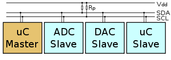
Pull-up resistor
Pull-up resistors are used in electronic logic circuits to ensure that inputs to logic systems settle at expected logic levels if external devices are disconnected or high-impedance...
with resistor
Resistor
A linear resistor is a linear, passive two-terminal electrical component that implements electrical resistance as a circuit element.The current through a resistor is in direct proportion to the voltage across the resistor's terminals. Thus, the ratio of the voltage applied across a resistor's...
s. Typical voltages used are +5 V or +3.3 V although systems with other voltages are permitted.
The I²C reference design
Reference design
Reference design refers to a technical blueprint of a system that is intended for others to copy. It contains the essential elements of the system; however, third parties may enhance or modify the design as required....
has a 7-bit or a 10-bit (depending on the device used) address space
Address space
In computing, an address space defines a range of discrete addresses, each of which may correspond to a network host, peripheral device, disk sector, a memory cell or other logical or physical entity.- Overview :...
. Common I²C bus speeds are the 100 kbit/s standard mode and the 10 kbit/s low-speed mode, but arbitrarily low clock frequencies are also allowed. Recent revisions of I²C can host more nodes and run at faster speeds (400 kbit/s Fast mode, 1 Mbit/s Fast mode plus or Fm+, and 3.4 Mbit/s High Speed mode). These speeds are more widely used on embedded systems than on PCs. There are also other features, such as 16-bit addressing.
Note that the bit rates quoted are for the transactions between master and slave without clock stretching or other hardware overhead. Protocol overheads include a slave address and perhaps a register address within the slave device as well as per-byte ACK/NACK bits. So the actual transfer rate of user data is lower than those peak bit rates alone would imply. For example, if each interaction with a slave inefficiently allows only 1 byte of data to be transferred, the data rate will be less than half the peak bit rate.
The maximum number of nodes is limited by the address space, and also by the total bus capacitance
Capacitance
In electromagnetism and electronics, capacitance is the ability of a capacitor to store energy in an electric field. Capacitance is also a measure of the amount of electric potential energy stored for a given electric potential. A common form of energy storage device is a parallel-plate capacitor...
of 400 pF, which restricts practical communication distances to a few meters.
Reference design
The reference design, as mentioned above, is a bus with a clockClock signal
In electronics and especially synchronous digital circuits, a clock signal is a particular type of signal that oscillates between a high and a low state and is utilized like a metronome to coordinate actions of circuits...
(SCL) and data (SDA) lines with 7-bit addressing.
The bus has two roles for nodes: master and slave:
- Master node — node that issues the clock and addresses slaves
- Slave node — node that receives the clock line and address.
The bus is a multi-master bus
Multi-master bus
A multi-master bus is a computer bus in which there are multiple bus master nodes present on the bus.This is used when multiple nodes on the bus must/need to initiate transfer....
which means any number of master nodes can be present.
Additionally, master and slave roles may be changed between messages (after a STOP is sent).
There are four potential modes of operation for a given bus device, although most devices only use a single role and its two modes:
- master transmitTransmission (telecommunications)Transmission, in telecommunications, is the process of sending, propagating and receiving an analogue or digital information signal over a physical point-to-point or point-to-multipoint transmission medium, either wired, optical fiber or wireless...
— master node is sending data to a slave - master receive — master node is receiving data from a slave
- slave transmit — slave node is sending data to the master
- slave receive — slave node is receiving data from the master
The master is initially in master transmit mode by sending a start bit followed by the 7-bit address of the slave it wishes to communicate with, which is finally followed by a single bit representing whether it wishes to write(0) to or read(1) from the slave.
If the slave exists on the bus then it will respond with an ACK
Acknowledgement (data networks)
In data networking, an acknowledgment is a signal passed between communicating processes or computers to signify acknowledgment, or receipt of response, as part of a communications protocol...
bit (active low for acknowledged) for that address. The master then continues in either transmit or receive mode (according to the read/write bit it sent), and the slave continues in its complementary mode (receive or transmit, respectively).
The address and the data bytes are sent most significant bit
Most significant bit
In computing, the most significant bit is the bit position in a binary number having the greatest value...
first.
The start bit is indicated by a high-to-low transition of SDA with SCL high; the stop bit is indicated by a low-to-high transition of SDA with SCL high.
If the master wishes to write to the slave then it repeatedly sends a byte with the slave sending an ACK bit. (In this situation, the master is in master transmit mode and the slave is in slave receive mode.)
If the master wishes to read from the slave then it repeatedly receives a byte from the slave, the master sending an ACK bit after every byte but the last one. (In this situation, the master is in master receive mode and the slave is in slave transmit mode.)
The master then ends transmission with a stop bit, or it may send another START bit if it wishes to retain control of the bus for another transfer (a "combined message").
Message protocols
I²C defines three basic types of messages, each of which begins with a START and ends with a STOP:- Single message where a master writes data to a slave;
- Single message where a master reads data from a slave;
- Combined messages, where a master issues at least two reads and/or writes to one or more slaves.
In a combined message, each read or write begins with a START and the slave address. After the first START, these are also called repeated START bits; repeated START bits are not preceded by STOP bits, which is how slaves know the next transfer is part of the same message.
Any given slave will only respond to particular messages, as defined by its product documentation.
Pure I²C systems support arbitrary message structures. SMBus is restricted to nine of those structures, such as read word N and write word N, involving a single slave. PMBus
PMBus
The Power Management Bus is a variant of the System Management Bus which is targeted at digital management of power supplies. Like SMBus, it is a relatively slow speed two wire communications protocol based on I²C...
extends SMBus with a Group protocol, allowing multiple such SMBus transactions to be sent in one combined message. The terminating STOP indicates when those grouped actions should take effect. For example, one PMBus operation might reconfigure three power supplies (using three different I2C slave addresses), and their new configurations would take effect at the same time: when they receive that STOP.
With only a few exceptions, neither I²C nor SMBus define message semantics, such as the meaning of data bytes in messages. Message semantics are otherwise product-specific. Those exceptions include messages addressed to the I²C general call address (0x00) or to the SMBus Alert Response Address; and messages involved in the SMBus Address Resolution Protocol (ARP) for dynamic address allocation and management.
In practice, most slaves adopt request/response control models, where one or more bytes following a write command are treated as a command or address. Those bytes determine how subsequent written bytes are treated and/or how the slave responds on subsequent reads. Most SMBus operations involve single byte commands.
Messaging example: 24c32 EEPROM
One specific example is the 24c32 type EEPROMEEPROM
EEPROM stands for Electrically Erasable Programmable Read-Only Memory and is a type of non-volatile memory used in computers and other electronic devices to store small amounts of data that must be saved when power is removed, e.g., calibration...
, which uses two request bytes that are called Address High and Address Low. (Accordingly, these EEPROMs aren't usable by pure SMBus hosts, which only support single byte commands or addresses.) These bytes are used to address bytes within the 32 kbit
Kilobit
The kilobit is a multiple of the unit bit for digital information or computer storage. The prefix kilo is defined in the International System of Units as a multiplier of 103 , and therefore,...
(4 kB
Kilobyte
The kilobyte is a multiple of the unit byte for digital information. Although the prefix kilo- means 1000, the term kilobyte and symbol KB have historically been used to refer to either 1024 bytes or 1000 bytes, dependent upon context, in the fields of computer science and information...
) supported by that EEPROM; the same two byte addressing is also used by larger EEPROMs, such as 24c512 ones storing 512 kbits (64 kB). Writing and reading data to these EEPROMs uses a simple protocol: the address is written, and then data is transferred until the end of the message. (That data transfer part of the protocol also makes trouble for SMBus, since the data bytes are not preceded by a count and more than 32 bytes can be transferred at once. I2C EEPROMs smaller than 32 kbits, such as 2 kbit 24c02 ones, are often used on SMBus with inefficient single byte data transfers.)
To write to the EEPROM, a single message is used. After the START, the master sends the chip's bus address with the direction bit clear (write), then sends the two byte address of data within the EEPROM and then sends data bytes to be written starting at that address, followed by a STOP. When writing multiple bytes, all the bytes must be in the same 32 byte page. While it's busy saving those bytes to memory, the EEPROM won't respond to further I2C requests. (That's another incompatibility with SMBus: SMBus devices must always respond to their bus addresses.)
To read starting at a particular address in the EEPROM, a combined message is used. After a START, the master first writes that chip's bus address with the direction bit clear (write) and then the two bytes of EEPROM data address. It then sends a (repeated) START and the EEPROM's bus address with the direction bit set (read). The EEPROM will then respond with the data bytes beginning at the specified EEPROM data address—a combined message, first a write then a read. The master issues a STOP after the first data byte it NACKs rather than ACKs (when it's read all it wants). The EEPROM increments the address after each data byte transferred; multi-byte reads can retrieve the entire contents of the EEPROM using one combined message.
Physical layer
At the physical layerPhysical layer
The physical layer or layer 1 is the first and lowest layer in the seven-layer OSI model of computer networking. The implementation of this layer is often termed PHY....
, both SCL & SDA lines are of open-drain design, thus, pull-up resistor
Pull-up resistor
Pull-up resistors are used in electronic logic circuits to ensure that inputs to logic systems settle at expected logic levels if external devices are disconnected or high-impedance...
s are needed.
Pulling the line to ground is considered a logical zero while letting the line float is a logical one.
This is used as a channel access method. High speed systems (and some others) also add a current source
Current source
A current source is an electrical or electronic device that delivers or absorbs electric current. A current source is the dual of a voltage source. The term constant-current sink is sometimes used for sources fed from a negative voltage supply...
pull up, at least on SCL; this supports faster rise times and higher bus capacitance.
An important consequence of this is that multiple nodes may be driving the lines simultaneously. If any node is driving the line low, it will be low. Nodes that are trying to transmit a logical one (i.e. letting the line float high) can see this, and thereby know that another node is active at the same time.
When used on SCL, this is called "clock stretching" and gives slaves a flow control mechanism. When used on SDA, this is called arbitration
Arbitration
Arbitration, a form of alternative dispute resolution , is a legal technique for the resolution of disputes outside the courts, where the parties to a dispute refer it to one or more persons , by whose decision they agree to be bound...
and ensures there is only one transmitter at a time.
When idle, both lines are high. To start a transaction, SDA is pulled low while SCL remains high. Releasing SDA to float high again would be a stop marker, signalling the end of a bus transaction. Although legal, this is typically pointless immediately after a start, so the next step is to pull SCL low.
Except for the start and stop signals, the SDA line only changes while the clock is low; transmitting a data bit consists of pulsing the clock line high while holding the data line steady at the desired level.
While SCL is low, the transmitter (initially the master) sets SDA to the desired value and (after a small delay to let the value propagate) lets SCL float high. The master then waits for SCL to actually go high; this will be delayed by the finite rise-time of the SCL signal (the RC time constant
RC time constant
In an RC circuit, the value of the time constant is equal to the product of the circuit resistance and the circuit capacitance , i.e. \tau = R × C. It is the time required to charge the capacitor, through the resistor, to 63.2 percent of full charge; or to discharge it to 36.8 percent of its...
of the pull-up resistor
Pull-up resistor
Pull-up resistors are used in electronic logic circuits to ensure that inputs to logic systems settle at expected logic levels if external devices are disconnected or high-impedance...
and the parasitic capacitance
Parasitic capacitance
In electrical circuits, parasitic capacitance, stray capacitance or, when relevant, self-capacitance , is an unavoidable and usually unwanted capacitance that exists between the parts of an electronic component or circuit simply because of their proximity to each other...
of the bus), and may be additionally delayed by a slave's clock stretching.
Once SCL is high, and the master waits a minimum time (4 μs for standard speed I²C) to ensure the receiver has seen the bit, then pulls it low again. This completes transmission of one bit.
After every 8 data bits in one direction, an "acknowledge" bit is transmitted in the other. The transmitter and receiver switch roles for one bit and the erstwhile receiver transmits a single 0 bit (ACK) back. If the transmitter sees a 1 bit (NACK) instead, it learns that:
- (If master transmitting to slave) The slave is unable to accept the data. No such slave, command not understood, or unable to accept any more data.
- (If slave transmitting to master) The master wishes the transfer to stop after this data byte.
After the acknowledge bit, the master may do one of three things:
- Prepare to transfer another byte of data: the transmitter set SDA, and the master pulses SCL high..
- Send a "Stop": Set SDA low, let SCL go high, then let SDA go high. This releases the I²C bus.
- Send a "Repeated start": Set SDA high, let SCL go high, and pull SDA low again. This starts a new I²C bus transaction without releasing the bus.
Clock stretching using SCL
One of the more significant features of the I²C protocol is clock stretching. An addressed slave device may hold the clock line (SCL) low after receiving (or sending) a byte, indicating that it is not yet ready to process more data. The master that is communicating with the slave may not finish the transmission of the current bit, but must wait until the clock line actually goes high. If the slave is clock stretching, the clock line will still be low (because the connections are open-drain). The same is true if a second, slower, master tries to drive the clock at the same time. (If there is more than one master, all but one of them will normally lose arbitration.)The master must wait until it observes the clock line going high, and an additional minimum time (4 μs for standard 100 kbit/s I²C) before pulling the clock low again.
Although the master may also hold the SCL line low for as long as it desires, the term "clock stretching" is normally used only when slaves do it. Although in theory any clock pulse may be stretched, generally it is the intervals before or after the acknowledgment bit which are used. For example, if the slave is a microcontroller
Microcontroller
A microcontroller is a small computer on a single integrated circuit containing a processor core, memory, and programmable input/output peripherals. Program memory in the form of NOR flash or OTP ROM is also often included on chip, as well as a typically small amount of RAM...
, its I²C interface will stretch the clock after each byte, until the software decides whether to sent a positive acknowledgment or a NACK.
Clock stretching is the only time in I2C where the slave drives SCL. Many slaves do not need to clock stretch and thus treat SCL as strictly a input with no circuitry to drive it. Some masters, such as those found inside custom ASIC
ASIC
ASIC may refer to:* Application-specific integrated circuit, an integrated circuit developed for a particular use, as opposed to a customised general-purpose device.* ASIC programming language, a dialect of BASIC...
s may not support clock stretching; often these devices will be labeled as a "two-wire interface" and not I²C.
To ensure a minimum bus throughput
Throughput
In communication networks, such as Ethernet or packet radio, throughput or network throughput is the average rate of successful message delivery over a communication channel. This data may be delivered over a physical or logical link, or pass through a certain network node...
, SMBus places limits on how far clocks may be stretched. Hosts and slaves adhering to those limits can't block access to the bus for more than a short time, which is not a guarantee made by pure I²C systems.
Arbitration using SDA
Every master monitors the bus for start and stop bits, and does not start a message while another master is keeping the bus busy. However, two masters may start transmission at about the same time; in this case, arbitration occurs. Slave transmit mode can also be arbitrated, when a master addresses multiple slaves, but this is less common. In contrast to protocols (such as EthernetEthernet
Ethernet is a family of computer networking technologies for local area networks commercially introduced in 1980. Standardized in IEEE 802.3, Ethernet has largely replaced competing wired LAN technologies....
) that use random back-off delays before issuing a retry, I²C has a deterministic arbitration policy. Each transmitter checks the level of the data line (SDA) and compares it with the levels it expects; if they don't match, that transmitter has lost arbitration, and drops out of this protocol interaction.
If one transmitter sets SDA to 1 (not driving a signal) and a second transmitter sets it to 0 (pull to ground), the result is that the line is low. The first transmitter then observes that the level of the line is different than expected, and concludes that another node is transmitting. The first node to notice such a difference is the one that loses arbitration: it stops driving SDA. If it's a master, it also stops driving SCL and waits for a STOP; then it may try to reissue its entire message. In the meantime, the other node has not noticed any difference between the expected and actual levels on SDA, and therefore continues transmission. It can do so without problems because so far the signal has been exactly as it expected; no other transmitter has disturbed its message.
If the two masters are sending a message to two different slaves, the one sending the lower slave address always "wins" arbitration in the address stage. Since the two masters may send messages to the same slave address—and addresses sometimes refer to multiple slaves—arbitration must continue into the data stages.
Arbitration occurs very rarely, but is necessary for proper multi-master support. As with clock-stretching, not all devices support arbitration. Those that do generally label themselves as supporting "multi-master" communication.
In the extremely rare case that two masters simultaneously send identical messages. then both will regard the communication as successful, but the slave will only see one message. Slaves that can be accessed by multiple masters must have commands that are idempotent for this reason.
Arbitration in SMBus
While I²C only arbitrates between masters, SMBus uses arbitration in three additional contexts, where multiple slaves respond to the master, and one gets its message through.
- Although conceptually a single-master bus, a slave device that supports the "host notify protocol" acts as a master to perform the notification. It seizes the bus and writes a 3-byte message to the reserved "SMBus Host" address (0x08), passing its address and two bytes of data. When two slaves try to notify the host at the same time, one of them will lose arbitration and need to retry.
- An alternative slave notification system uses the separate SMBALERT# signal to request attention. In this case, the host performs a 1-byte read from the reserved "SMBus Alert Response Address" (0x0c), which is a kind of broadcast address. All alerting slaves respond with a data bytes containing their own address. When the slave successfully transmits its own address (winning arbitration against others) it stops raising that interrupt. In both this and the preceding case, arbitration ensures that one slave's message will be received, and the others will know they must retry.
- SMBus also supports an "address resolution protocol", wherein devices return a 16-byte "universal device ID" (UDID). Multiple devices may respond; the one with the least UDID will win arbitration and be recognized.
Buffering and Muxing
When there are many I2C devices in a system there can be a need to include bus buffers or multiplexers to split large bus segments into smaller ones. This can be necessary to keep the capacitance of a bus segment below the allowable value or to allow multiple devices with the same address to be separated by a multiplexer. Many types of multiplexers and buffers exist and all must take into account the fact that I2C lines are specified to be bidirectional. Multiplexers can be implemented with analog switches which can tie one segment to another. Analog switches maintain the bi-directional nature of the lines but do not isolate the capacitance of one segment from another or provide buffering capability.Buffers can be used to isolate capacitance on one segment from another and/or allow I2C to be sent over longer cables or traces. Buffers for bi-directional lines such as I2C must use one of several schemes for preventing latch-up. I2C is open-drain so buffers must drive a low on one side when they see a low on the other. One method for preventing latch-up is for a buffer to have carefully selected input and output levels such that the output level of its driver is higher than it's input threshold, preventing it from triggering itself. For example, a buffer may have an input threshold of 0.4V for detecting a low, but an output low level of 0.5V. This method requires that all other devices on the bus have thresholds which are compatible and often means that multiple buffers implementing this scheme cannot be put in series with one another.
Alternatively, other types of buffers exist that implement current amplifiers, or keep track of the state (i.e. which side drove the bus low) to prevent latch up. The state method typically means that an unintended pulse is created during a handoff when one side is driving the bus low, then the other drives it low, then the first side releases (this is common during an I2C acknowledgement).
Timing diagram
Example of bit-banging the I2C Master protocol
Below is an example of bit-banging the I²C protocol as an I²C master. The example is written in pseudo CC (programming language)
C is a general-purpose computer programming language developed between 1969 and 1973 by Dennis Ritchie at the Bell Telephone Laboratories for use with the Unix operating system....
. It illustrates all of the I²C features described before (clock stretching, arbitration, start/stop bit, ack/nack)
/* Hardware-Specific Support Functions That MUST Be Customized */
- define I2CSPEED 100
void I2CDELAY {volatile int v; int i; for(i=0;i
bool READSDA(void) {return 1;} /* Set SDA as input and return current level of line, 0 or 1 */
void CLRSCL(void) {} /* Actively drive SCL signal low */
void CLRSDA(void) {} /* Actively drive SDA signal low */
void ARBITRATION_LOST(void) {}
/* Global Data */
bool started = false;
void i2c_start_cond(void)
{
/* if started, do a restart cond */
if (started) {
/* set SDA to 1 */
READSDA;
I2CDELAY;
/* Clock stretching */
while (READSCL
0)
; /* You should add timeout to this loop */
}
if (READSDA
0)ARBITRATION_LOST;
/* SCL is high, set SDA from 1 to 0 */
CLRSDA;
I2CDELAY;
CLRSCL;
started = true;
}
void i2c_stop_cond(void)
{
/* set SDA to 0 */
CLRSDA;
I2CDELAY;
/* Clock stretching */
while (READSCL
0)
; /* You should add timeout to this loop */
/* SCL is high, set SDA from 0 to 1 */
if (READSDA
0)ARBITRATION_LOST;
I2CDELAY;
started = false;
}
/* Write a bit to I2C bus */
void i2c_write_bit(bool bit)
{
if (bit)
READSDA;
else
CLRSDA;
I2CDELAY;
/* Clock stretching */
while (READSCL
0)
; /* You should add timeout to this loop */
/* SCL is high, now data is valid */
/* If SDA is high, check that nobody else is driving SDA */
if (bit && READSDA
0)ARBITRATION_LOST;
I2CDELAY;
CLRSCL;
}
/* Read a bit from I2C bus */
bool i2c_read_bit(void)
{
bool bit;
/* Let the slave drive data */
READSDA;
I2CDELAY;
/* Clock stretching */
while (READSCL 0)
; /* You should add timeout to this loop */
/* SCL is high, now data is valid */
bit = READSDA;
I2CDELAY;
CLRSCL;
return bit;
}
/* Write a byte to I2C bus. Return 0 if ack by the slave */
bool i2c_write_byte(bool send_start, bool send_stop, unsigned char byte)
{
unsigned bit;
bool nack;
if (send_start)
i2c_start_cond;
for (bit = 0; bit < 8; bit++) {
i2c_write_bit((byte & 0x80) != 0);
byte <<= 1;
}
nack = i2c_read_bit;
if (send_stop)
i2c_stop_cond;
return nack;
}
/* Read a byte from I2C bus */
unsigned char i2c_read_byte(bool nack, bool send_stop)
{
unsigned char byte = 0;
unsigned bit;
for (bit = 0; bit < 8; bit++)
byte = (byte << 1) | i2c_read_bit;
i2c_write_bit(nack);
if (send_stop)
i2c_stop_cond;
return byte;
}
Applications
I²C is appropriate for peripherals where simplicity and low manufacturing cost are more important than speed. Common applications of the I²C bus are:
- Reading configuration data from SPDSerial Presence DetectSerial presence detect refers to a standardized way to automatically access information about a computer memory module. Earlier 72-pin SIMMs included 5 pins which provided 5 bits of parallel presence detect data, but the 168-pin DIMM standard changed to a serial presence detect to encode much...
EEPROMs on SDRAMSDRAMSynchronous dynamic random access memory is dynamic random access memory that is synchronized with the system bus. Classic DRAM has an asynchronous interface, which means that it responds as quickly as possible to changes in control inputs...
, DDR SDRAMDDR SDRAMDouble data rate synchronous dynamic random access memory is a class of memory integrated circuits used in computers. DDR SDRAM has been superseded by DDR2 SDRAM and DDR3 SDRAM, neither of which are either forward or backward compatible with DDR SDRAM, meaning that DDR2 or DDR3 memory modules...
, DDR2 SDRAMDDR2 SDRAMDDR2 SDRAM is a double data rate synchronous dynamic random-access memory interface. It supersedes the original DDR SDRAM specification and has itself been superseded by DDR3 SDRAM...
memory sticks (DIMMDIMMA DIMM or dual in-line memory module, comprises a series of dynamic random-access memory integrated circuits. These modules are mounted on a printed circuit board and designed for use in personal computers, workstations and servers...
) and other stacked PC boards - Supporting systems management for PCI cards, through an SMBusSystem Management BusThe System Management Bus is a single-ended simple two-wire bus for the purpose of lightweight communication...
2.0 connection. - Accessing NVRAMNVRAMNon-volatile random-access memory is random-access memory that retains its information when power is turned off, which is described technically as being non-volatile...
chips that keep user settings. - Accessing low speed DACsDigital-to-analog converterIn electronics, a digital-to-analog converter is a device that converts a digital code to an analog signal . An analog-to-digital converter performs the reverse operation...
and ADCsAnalog-to-digital converterAn analog-to-digital converter is a device that converts a continuous quantity to a discrete time digital representation. An ADC may also provide an isolated measurement...
. - Changing contrast, hue, and color balance settings in monitors (Display Data ChannelDisplay Data ChannelThe Display Data Channel or DDC is a collection of digital communication protocols between a computer display and a graphics adapter that enables the display to communicate its supported display modes to the adapter and to enable the computer host to adjust monitor parameters, such as brightness...
). - Changing sound volume in intelligent speakers.
- Controlling OLEDOrganic light-emitting diodeAn OLED is a light-emitting diode in which the emissive electroluminescent layer is a film of organic compounds which emit light in response to an electric current. This layer of organic semiconductor material is situated between two electrodes...
/LCDLiquid crystal displayA liquid crystal display is a flat panel display, electronic visual display, or video display that uses the light modulating properties of liquid crystals . LCs do not emit light directly....
displays, like in a cellphone. - Reading hardware monitors and diagnostic sensors, like a CPU thermostat and fan speed.
- Reading real-time clockReal-time clockA real-time clock is a computer clock that keeps track of the current time. Although the term often refers to the devices in personal computers, servers and embedded systems, RTCs are present in almost any electronic device which needs to keep accurate time.-Terminology:The term is used to avoid...
s. - Turning on and turning off the power supply of system components.
A particular strength of I²C is that a microcontroller
Microcontroller
A microcontroller is a small computer on a single integrated circuit containing a processor core, memory, and programmable input/output peripherals. Program memory in the form of NOR flash or OTP ROM is also often included on chip, as well as a typically small amount of RAM...
can control a network of device chips with just two general-purpose I/O pins and software. Many other bus technologies used in similar applications, such as Serial Peripheral Interface Bus
Serial Peripheral Interface Bus
The Serial Peripheral Interface Bus or SPI bus is a synchronous serial data link standard named by Motorola that operates in full duplex mode. Devices communicate in master/slave mode where the master device initiates the data frame. Multiple slave devices are allowed with individual slave select ...
, require more pins and signals to connect devices.
Operating system support
- In Microsoft WindowsMicrosoft WindowsMicrosoft Windows is a series of operating systems produced by Microsoft.Microsoft introduced an operating environment named Windows on November 20, 1985 as an add-on to MS-DOS in response to the growing interest in graphical user interfaces . Microsoft Windows came to dominate the world's personal...
, I²C is implemented by the respective device drivers of much of the industry's available hardware. - In Mac OS XMac OS XMac OS X is a series of Unix-based operating systems and graphical user interfaces developed, marketed, and sold by Apple Inc. Since 2002, has been included with all new Macintosh computer systems...
, there are about two dozen I²C kernel extensions which communicate with sensors for reading voltage, current, temperature, motion, and other physical status. - In LinuxLinuxLinux is a Unix-like computer operating system assembled under the model of free and open source software development and distribution. The defining component of any Linux system is the Linux kernel, an operating system kernel first released October 5, 1991 by Linus Torvalds...
, I²C is handled with a device driver for the specific device, and another for the I²C (or SMBusSystem Management BusThe System Management Bus is a single-ended simple two-wire bus for the purpose of lightweight communication...
) adapter to which it's connected. Several hundred such drivers are part of current releases. - FreeBSDFreeBSDFreeBSD is a free Unix-like operating system descended from AT&T UNIX via BSD UNIX. Although for legal reasons FreeBSD cannot be called “UNIX”, as the direct descendant of BSD UNIX , FreeBSD’s internals and system APIs are UNIX-compliant...
, NetBSDNetBSDNetBSD is a freely available open source version of the Berkeley Software Distribution Unix operating system. It was the second open source BSD descendant to be formally released, after 386BSD, and continues to be actively developed. The NetBSD project is primarily focused on high quality design,...
and OpenBSDOpenBSDOpenBSD is a Unix-like computer operating system descended from Berkeley Software Distribution , a Unix derivative developed at the University of California, Berkeley. It was forked from NetBSD by project leader Theo de Raadt in late 1995...
also provide an I²C framework, with support for a number of common master controllers and sensors. - In Sinclair QDOSSinclair QDOSQDOS is the multitasking operating system found on the Sinclair QL personal computer and its clones...
and MinervaMinerva (QDOS reimplementation)Written by Laurence Reeves in England, Minerva was a reimplementation of Sinclair QDOS, the built-in operating system of the Sinclair QL line of personal computers. Minerva incorporated many bug fixes and enhancements to both QDOS and the SuperBASIC programming language...
QLSinclair QLThe Sinclair QL , was a personal computer launched by Sinclair Research in 1984, as the successor to the Sinclair ZX Spectrum...
operating systems I²C is supported via a set of extensions provided by TF Services. - In AmigaOSAmigaOSAmigaOS is the default native operating system of the Amiga personal computer. It was developed first by Commodore International, and initially introduced in 1985 with the Amiga 1000...
one can use the i2c.resource component for AmigaOS 4.x or the shared library i2c.library by Wilhelm Noeker for older systems. - eCosECoseCos is an open source, royalty-free, real-time operating system intended for embedded systems and applications which need only one process with multiple threads. It is designed to be customizable to precise application requirements of run-time performance and hardware needs...
supports I²C for several hardware architectures. - ArduinoArduinoArduino is an open-source single-board microcontroller, descendant of the open-source Wiring platform, designed to make the process of using electronics in multidisciplinary projects more accessible. The hardware consists of a simple open hardware design for the Arduino board with an Atmel AVR...
developers can use the 'Wire' library.
Development tools
When developing or troubleshooting systems using I2C, visibility at the level of hardware signals can be important.
I²C host adapters
There are a number of hardwareHardware
Hardware is a general term for equipment such as keys, locks, hinges, latches, handles, wire, chains, plumbing supplies, tools, utensils, cutlery and machine parts. Household hardware is typically sold in hardware stores....
solutions for host computers, running Linux
Linux
Linux is a Unix-like computer operating system assembled under the model of free and open source software development and distribution. The defining component of any Linux system is the Linux kernel, an operating system kernel first released October 5, 1991 by Linus Torvalds...
, Mac
Macintosh
The Macintosh , or Mac, is a series of several lines of personal computers designed, developed, and marketed by Apple Inc. The first Macintosh was introduced by Apple's then-chairman Steve Jobs on January 24, 1984; it was the first commercially successful personal computer to feature a mouse and a...
or Windows
Microsoft Windows
Microsoft Windows is a series of operating systems produced by Microsoft.Microsoft introduced an operating environment named Windows on November 20, 1985 as an add-on to MS-DOS in response to the growing interest in graphical user interfaces . Microsoft Windows came to dominate the world's personal...
, I²C master and/or slave capabilities. Most of them are based on Universal Serial Bus
Universal Serial Bus
USB is an industry standard developed in the mid-1990s that defines the cables, connectors and protocols used in a bus for connection, communication and power supply between computers and electronic devices....
(USB) to I²C adapters. Not all of them require proprietary drivers or APIs
Application programming interface
An application programming interface is a source code based specification intended to be used as an interface by software components to communicate with each other...
.
I²C protocol analyzers
I²C Protocol Analyzers are tools which sample an I²C bus and decode the electrical signals to provide a higher-level view of the data being transmitted on the bus.Logic analyzers
When developing and/or troubleshooting the I²C bus, examination of hardware signals can be very important. Logic analyzers are tools which collect, analyze, decode, store signals so people can view the high-speed waveforms at their leisure. Logic analzyers display time-stamps of each signal level change, which can help find protocol problems. Most logic analyzers have the capability to decode bus signals into high-level protocol data and show ASCII data.Revisions
- In 1982, the original I²C system was created as a simple internal bus system for building control electronics with various Philips chips.
- In 1992, Version 1.0 (the first standardized version) added a new fast mode at 400 kbit/s and a 10-bit addressing mode to increase capacity to 1008 nodes.
- In 1998, Version 2.0 added high-speed mode at 3.4 Mbit/s with power-saving requirements for electric voltage and current.
- In 2000, Version 2.1 introduced a minor cleanup of version 2.0.
- In 2007, Version 3.0 added Fast mode plus ("Fm+") and a device ID mechanism; it is the most recent standard.
Limitations
The assignment of slave addresses is one weakness of I²C. Seven bits is too few to prevent address collisions between the many thousands of available devices, and manufacturers rarely dedicate enough pins to configure the full slave address used on a given board. Three pins is typical, giving only eight choices of slave address. While some devices can set multiple address bits per pin, e.g. by using a spare internal ADC channel to sense one of eight ranges set by an external voltage divider, usually each pin controls one address bit. Manufacturers may provide pins to configure a few low order bits of the address and arbitrarily set the higher order bits to some value based on the model. This limits the number of devices of that model which may be present on the same bus to some low number, typically between two and eight.
That partially addresses the issue of address collisions between different vendors.
Ten-bit I²C addresses are not yet widely used. , and many host operating systems don't support them.
Neither is the complex SMBus "ARP" scheme for dynamically assigning addresses (other than for PCI cards with SMBus presence, for which it is required).
Automatic bus configuration is a related issue. A given address may be used by a number of different protocol-incompatible devices in various systems, and hardly any device types can be detected at runtime. For example
0x51 may be used by a 24LC02 or 24C32 EEPROMEEPROM
EEPROM stands for Electrically Erasable Programmable Read-Only Memory and is a type of non-volatile memory used in computers and other electronic devices to store small amounts of data that must be saved when power is removed, e.g., calibration...
, with incompatible addressing; or by a PCF8563 RTC
Real-time clock
A real-time clock is a computer clock that keeps track of the current time. Although the term often refers to the devices in personal computers, servers and embedded systems, RTCs are present in almost any electronic device which needs to keep accurate time.-Terminology:The term is used to avoid...
, which can't reliably be distinguished from either (without changing device state, which might not be allowed). The only reliable configuration mechanisms available to hosts involve out-of-band mechanisms such as tables provided by system firmware which list the available devices. Again, this issue can partially be addressed by ARP in SMBus systems, especially when vendor and product identifiers are used; but that hasn't really caught on. The rev 03 version of the I²C specification adds a device ID mechanism, which at this writing has not had time to catch on either.
I²C supports a limited range of speeds. Hosts supporting the multi-megabit speeds are rare. Support for the Fm+ one-megabit speed is more widespread, since its electronics are simple variants of what is used at lower speeds. Many devices don't support the 400 kbit/s speed (in part because SMBus doesn't yet support it). I²C nodes implemented in software (instead of dedicated hardware) may not even support the 100 kbit/s speed; so the whole range defined in the specification is rarely usable. All devices must at least partially support the highest speed used or they may spuriously detect their device address.
Devices are allowed to stretch clock cycles to suit their particular needs, which can starve bandwidth needed by faster devices and increase latencies when talking to other device addresses.
Bus capacitance also places a limit on the transfer speed, especially when current sources aren't used to decrease signal rise times.
Because I2C is a shared bus, there is the potential for any device to have a fault and hang the entire bus. For example if any device holds the SDA or SCL line low it prevents the master from sending START or STOP commands to reset the bus. Thus it's common for designs to include a reset signal that provides an external method of resetting the bus devices. However many devices do not have a dedicated reset pin forcing the designer to put in circuitry to allow devices to be power cycled if they need to be reset.
Because of these limits (address management, bus configuration, potential faults, speed), few I²C bus segments have even a dozen devices. It's common for systems to have several such segments. One might be dedicated to use with high speed devices, for low latency power management. Another might be used to control a few devices where latency and throughput aren't important issues; yet another segment might be used only to read EEPROM chips describing add-on cards (such as the SPD
Serial Presence Detect
Serial presence detect refers to a standardized way to automatically access information about a computer memory module. Earlier 72-pin SIMMs included 5 pins which provided 5 bits of parallel presence detect data, but the 168-pin DIMM standard changed to a serial presence detect to encode much...
standard used with DRAM sticks).
Derivative technologies
I²C is the basis for the ACCESS.bus
ACCESS.bus
ACCESS.bus is a peripheral-interconnect computer bus developed by Philips in the early 1990s. It is similar in purpose to USB, in that it allows low-speed devices to be added or removed from a computer on the fly...
, the VESA
VESA
VESA is an international standards body for computer graphics founded in 1989 by NEC Home Electronics and eight other video display adapter manufacturers.VESA's initial goal was to produce a standard for 800×600 SVGA resolution video displays...
Display Data Channel
Display Data Channel
The Display Data Channel or DDC is a collection of digital communication protocols between a computer display and a graphics adapter that enables the display to communicate its supported display modes to the adapter and to enable the computer host to adjust monitor parameters, such as brightness...
(DDC) interface, the System Management Bus
System Management Bus
The System Management Bus is a single-ended simple two-wire bus for the purpose of lightweight communication...
(SMBus), Power Management Bus (PMBus) and the Intelligent Platform Management Bus (IPMB, one of the protocols of IPMI
Intelligent Platform Management Interface
The Intelligent Platform Management Interface is a standardizedcomputer system interface used by system administrators to manage a computer system and monitor its operation....
). These implementations have differences in voltage and clock frequency ranges, and may have interrupt lines
Interrupt request
The computing phrase "interrupt request" is used to refer to either the act of interrupting the bus lines used to signal an interrupt, or the interrupt input lines on a Programmable Interrupt Controller...
.
TWI (Two Wire Interface) or TWSI (Two-Wire Serial Interface) is essentially the same bus implemented on various system-on-chip processors from Atmel
Atmel
Atmel Corporation is a manufacturer of semiconductors, founded in 1984. Its focus is on system-level solutions built around flash microcontrollers...
and other vendors. Vendors use the name TWI, even though I²C is not a registered trademark. Trademark protection only exists for the respective logo (See upper right corner) and patents on I²C have now lapsed.
See also
- Related Buses
- List of network buses
- SMBus
- PMBusPMBusThe Power Management Bus is a variant of the System Management Bus which is targeted at digital management of power supplies. Like SMBus, it is a relatively slow speed two wire communications protocol based on I²C...
- ACCESS.busACCESS.busACCESS.bus is a peripheral-interconnect computer bus developed by Philips in the early 1990s. It is similar in purpose to USB, in that it allows low-speed devices to be added or removed from a computer on the fly...
- Related Connectors:
- Serial Presence DetectSerial Presence DetectSerial presence detect refers to a standardized way to automatically access information about a computer memory module. Earlier 72-pin SIMMs included 5 pins which provided 5 bits of parallel presence detect data, but the 168-pin DIMM standard changed to a serial presence detect to encode much...
(SPD) - Common in DRAM memory modules. - Display Data ChannelDisplay Data ChannelThe Display Data Channel or DDC is a collection of digital communication protocols between a computer display and a graphics adapter that enables the display to communicate its supported display modes to the adapter and to enable the computer host to adjust monitor parameters, such as brightness...
(DDC) - Used in video connectors, such as VGAVGA connectorA Video Graphics Array connector is a three-row 15-pin DE-15 connector. The 15-pin VGA connector is found on many video cards, computer monitors, and some high definition television sets...
, DVIDigital Visual InterfaceThe Digital Visual Interface is a video interface standard covering the transmission of video between a source device and a display device. The DVI standard has achieved widespread acceptance in the PC industry, both in desktop PCs and monitors...
, HDMIHDMIHDMI is a compact audio/video interface for transmitting uncompressed digital data. It is a digital alternative to consumer analog standards, such as radio frequency coaxial cable, composite video, S-Video, SCART, component video, D-Terminal, or VGA...
, DisplayPortDisplayPortDisplayPort is a digital display interface standard produced by the Video Electronics Standards Association . The specification defines a royalty-free digital interconnect for audio and video. The interface is primarily used to connect a video source to a display device such as a computer monitor...
. - UEXTUEXTUniveral EXTension is a connector layout which includes power and three serials buses: Asynchronous, I2C, SPI. The connector layout was specified by Olimex Ltd and declared an open-project that is royalty-free.-Physical characteristics:...
Connector.
- Serial Presence Detect
Further reading
- The I2C Bus : From Theory to Practice; Dominique Paret; 314 pages; 1997; ISBN 9780471962687.
External links Official Specification
Other Sources
- Detailed Introduction, Primer
- Tackling I2C Development Complexities Using Innovative Tools
- Advanced I²C Bus Analysis Webinar
- I²C Background
- I²C Bus / Access Bus
- Using the I²C Bus with Linux
- Proven Implementations of the I²C Bus
- OpenBSD iic(4) manual page
- Lm-sensors, Linux package which supports sensors using the I²C bus, among others.
- massmind I²C page Source code, samples and technical information for using I²C with PC, PIC and SX microcontrollers.
- Serial buses information page
- I²C Bus Technical Overview and Frequently Asked Questions
- The Bus Buffer Resource. For 2-wire buses such as I²C, SMBus, PMBus, IPMB & IPMI
- I²C Protocol
- I²C logic microchips from Texas Instruments
- A commercial hardware implementation of I²C written in VHDL
- OpenCores open source hardware implementation, in VerilogVerilogIn the semiconductor and electronic design industry, Verilog is a hardware description language used to model electronic systems. Verilog HDL, not to be confused with VHDL , is most commonly used in the design, verification, and implementation of digital logic chips at the register-transfer level...
and VHDL - Introduction to I²C Bus
- Introduction to SPI and I2C protocols
- I2C Protocol Decode software
- Beginner's guide to using Arduino with I²C devices, including worked examples
- Effects of Varying I²C Pull-up Resistors