

Emitter-coupled logic
Encyclopedia
Logic family
In computer engineering, a logic family may refer to one of two related concepts. A logic family of monolithic digital integrated circuit devices is a group of electronic logic gates constructed using one of several different designs, usually with compatible logic levels and power supply...
that achieves high speed by using an overdriven BJT
Bipolar junction transistor
|- align = "center"| || PNP|- align = "center"| || NPNA bipolar transistor is a three-terminal electronic device constructed of doped semiconductor material and may be used in amplifying or switching applications. Bipolar transistors are so named because their operation involves both electrons...
differential amplifier with single-ended input, whose emitter current is limited to avoid the slow saturation region of transistor operation.
As the current is steered between the two legs of the emitter-coupled pair, ECL is sometimes called current-steering logic (CSL),
current-mode logic (CML)
or current-switch emitter-follower (CSEF) logic.
In ECL, the transistors are never in saturation, the input/output voltages have a small swing (0.8 V), the input impedance is high, and the output resistance is low; as a result, the transistors change states quickly, gate delays are low, and the fanout
Fanout
In digital electronics, the fan-out of a logic gate output is the number of gate inputs to which it is connected.In most designs, logic gates are connected together to form more complex circuits. While no more than one logic gate output is connected to any single input, it is common for one output...
capability is high. In addition, the complementary outputs decrease the propagation time of the whole circuit by saving additional inverters. ECL's major disadvantage is that the circuit continuously draws current, which means it requires a lot of power.
The equivalent of emitter-coupled logic made out of FETs
Field-effect transistor
The field-effect transistor is a transistor that relies on an electric field to control the shape and hence the conductivity of a channel of one type of charge carrier in a semiconductor material. FETs are sometimes called unipolar transistors to contrast their single-carrier-type operation with...
is called source-coupled FET logic (SCFL).
A variation of ECL in which all signals paths and gate inputs are differential is known as differential current switch (DCS) logic.
History
IBM
International Business Machines Corporation or IBM is an American multinational technology and consulting corporation headquartered in Armonk, New York, United States. IBM manufactures and sells computer hardware and software, and it offers infrastructure, hosting and consulting services in areas...
by Hannon S. Yourke. Originally called current-steering logic, it was used in the Stretch, IBM 7090
IBM 7090
The IBM 7090 was a second-generation transistorized version of the earlier IBM 709 vacuum tube mainframe computers and was designed for "large-scale scientific and technological applications". The 7090 was the third member of the IBM 700/7000 series scientific computers. The first 7090 installation...
, and IBM 7094 computers.
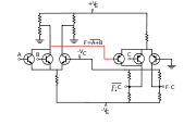
While ECL circuits in the mid-1960s through the 1990s consisted of a differential amplifier input stage to perform logic, followed by an emitter follower to drive outputs and shift the output voltages so they will be compatible with the inputs, Yourke's current switch, also known as ECL, consisted only of differential amplifiers. To provide compatible input and output levels, two complementary versions were used, an NPN version and a PNP version. The NPN output could drive PNP inputs, and vice-versa. "The disadvantages are that more different power supply voltages are needed, and both pnp and npn transistors are required."
Motorola
Motorola
Motorola, Inc. was an American multinational telecommunications company based in Schaumburg, Illinois, which was eventually divided into two independent public companies, Motorola Mobility and Motorola Solutions on January 4, 2011, after losing $4.3 billion from 2007 to 2009...
introduced their first digital monolithic integrated circuit line, MECL I, in 1962. Motorola developed several improved series, with MECL II in 1966, MECL III in 1968 with 1 nanosecond gate propagation time and 300 MHz flip-flop toggle rates, and the 10,000 series (with lower power consumption and controlled edge speeds) in 1971.
The drawbacks associated with ECL have meant that it has been used mainly when high performance is a vital requirement. Older high-end mainframe computers, such as the Enterprise System/9000 members of IBM's ESA/390
ESA/390
ESA/390 was introduced in September 1990 and is IBM's last 31-bit-address/32-bit-data mainframe computing design, copied by Amdahl, Hitachi, and Fujitsu among other competitors...
computer family, used ECL
as did the Cray-1
Cray-1
The Cray-1 was a supercomputer designed, manufactured, and marketed by Cray Research. The first Cray-1 system was installed at Los Alamos National Laboratory in 1976, and it went on to become one of the best known and most successful supercomputers in history...
; current IBM mainframes use CMOS
CMOS
Complementary metal–oxide–semiconductor is a technology for constructing integrated circuits. CMOS technology is used in microprocessors, microcontrollers, static RAM, and other digital logic circuits...
.
Implementation
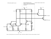
ECL is based on an emitter-coupled (long-tailed) pair, shaded red in the figure on the right. The left half of the pair (shaded yellow) consists of two parallel-connected input transistors T1 and T2 (an exemplary two-input gate is considered) implementing NOR logic. The base voltage of the right transistor T3 is held fixed by a reference voltage source, shaded light green: the voltage divider with a diode thermal compensation (R1, R2, D1 and D2) and sometimes a buffering emitter follower (not shown on the picture); thus the emitter voltages are kept relatively steady. As a result, the common emitter resistor RE acts nearly as a current sourceCurrent source
A current source is an electrical or electronic device that delivers or absorbs electric current. A current source is the dual of a voltage source. The term constant-current sink is sometimes used for sources fed from a negative voltage supply...
. The output voltages at the collector load resistors RC1 and RC3 are shifted and buffered to the inverting and non-inverting outputs by the emitter followers T4 and T5 (shaded blue). The output emitter resistors RE4 and RE5 do not exist in all versions of ECL. In some cases 50 Ω line termination resistors connected between the bases of the input transistors and −2 V act as emitter resistors.
Operation
The ECL circuit operation is considered below with assumption that the input voltage is applied to T1 base, while T2 input is unused or a logical "0" is applied.During the transition, the core of the circuit – the emitter-coupled pair (T1 and T3) – acts as a differential amplifier with single-ended input. The "long-tail" current source (RE) sets the total current flowing through the two legs of the pair. The input voltage controls the current flowing through the transistors by sharing it between the two legs, steering it all to one side when not near the switching point. The gain is higher than at the end states (see below) and the circuit switches quickly.
At low input voltage (logical "0") or at high input voltage (logical "1") the differential amplifier is overdriven. The one transistor (T1 or T3) is cut-off and the other (T3 or T1) is in active linear region acting as a common-emitter stage with emitter degeneration that takes all the current, starving the other cut-off transistor.
The active transistor is loaded with the relatively high emitter resistance RE that introduces a significant negative feedback (emitter degeneration). To prevent saturation of the active transistor so that the diffusion time that slows the recovery from saturation will not be involved in the logic delay, the emitter and collector resistances are chosen such that at maximum input voltage some voltage is left across the transistor. The residual gain is low (K = RC/RE < 1). The circuit is insensitive to the input voltage variations and the transistor stays firmly in active linear region. The input resistance is high because of the series negative feedback.
The cut-off transistor breaks the connection between its input and output. As a result, its input voltage does not affect the output voltage. The input resistance is high again since the base-emitter junction is cut-off.
Characteristics
Other noteworthy characteristics of the ECL family include the fact that the large current requirement is approximately constant, and does not depend significantly on the state of the circuit. This means that ECL circuits generate relatively little power noise, unlike many other logic types which typically draw far more current when switching than quiescent, for which power noise can become problematic. In cryptographic applications, ECL circuits are also less susceptible to side channel attackSide channel attack
In cryptography, a side channel attack is any attack based on information gained from the physical implementation of a cryptosystem, rather than brute force or theoretical weaknesses in the algorithms...
s such as differential power analysis.
The propagation time
Propagation delay
Propagation delay is a technical term that can have a different meaning depending on the context. It can relate to networking, electronics or physics...
for this arrangement can be less than a nanosecond, making it for many years the fastest logic family.
Power supplies and logic levels
The ECL circuits usually operate with negative power supplies (positive end of the supply is connected to ground) in contrast to other logic families in which negative end of the supply is grounded. This is done mainly to minimize the influence of the power supply variations on the logic levels as ECL is more sensitive to noise on the VCC and relatively immune to noise on VEE. Because ground should be the most stable voltage in a system, ECL is specified with a positive ground. In this connection, when the supply voltage varies, the voltage drops across the collector resistors change slightly (in the case of emitter constant current source, they do not change at all). As the collector resistors are firmly "tied up" to ground, the output voltages "move" slightly (or not at all). If the negative end of the power supply was grounded, the collector resistors would be attached to the positive rail. As the constant voltage drops across the collector resistors change slightly (or not at all), the output voltages follow the supply voltage variations and the two circuit parts act as constant current level shifters. In this case, the voltage divider R1-R2 compensates the voltage variations to some extent. The positive power supply has another disadvantage - the output voltages will vary slightly (±0.4 V) against the background of high constant voltage (+3.9 V). Another reason for using a negative power supply is protection of the output transistors from an accidental short circuit developing between output and ground (but the outputs are not protected from a short circuit with the negative rail).The value of the supply voltage is chosen so that a sufficient current to flow through the compensating diodes D1 and D2 and the voltage drop across the common emitter resistor RE to be adequate.
ECL circuits available on the open market usually operated with logic levels incompatible with other families. This meant that interoperation between ECL and other logic families, such as the popular TTL
Transistor-transistor logic
Transistor–transistor logic is a class of digital circuits built from bipolar junction transistors and resistors. It is called transistor–transistor logic because both the logic gating function and the amplifying function are performed by transistors .TTL is notable for being a widespread...
family, required additional interface circuits. The fact that the high and low logic levels are relatively close meant that ECL suffers from small noise margins, which can be troublesome.
At least one manufacturer, IBM
IBM
International Business Machines Corporation or IBM is an American multinational technology and consulting corporation headquartered in Armonk, New York, United States. IBM manufactures and sells computer hardware and software, and it offers infrastructure, hosting and consulting services in areas...
, made ECL circuits for use in the manufacturer's own products. The power supplies were substantially different from those used in the open market.
Positive emitter-coupled logic (PECL) is a further development of ECL using a positive 5V supply instead of a negative 5V supply. Low-voltage positive emitter-coupled logic (LVPECL) is a power optimized version of PECL , using a positive 3.3V instead of 5V supply. PECL and LVPECL are differential signaling systems, and are mainly used in high speed and clock distribution circuits.
Logic levels:
| Type | Vee | Vlow | Vhigh | Vcc | |
| PECL | GND | 3.4 V | 4.2 V | 5.0 V | |
| LVPECL | GND | 1.6 V | 2.4 V | 3.3 V | 2.0 V |