
Carrier recovery
Encyclopedia
A carrier recovery system is a circuit
used to estimate and compensate for frequency and phase differences between a received signal's carrier wave
and the receiver's local oscillator for the purpose of coherent demodulation
.
 In the transmitter of a communications carrier system
, a carrier wave is modulated by a baseband
signal. At the receiver the baseband information is extracted from the incoming modulated waveform. In an ideal communications system the carrier frequency
oscillators of the transmitter and receiver would be perfectly matched in frequency and phase thereby permitting perfect coherent demodulation of the modulated baseband signal. However, transmitters and receivers rarely share the same carrier frequency oscillator. Communications receiver systems are usually independent of transmitting systems and contain their own oscillators with frequency and phase offsets and instabilities. Doppler shift may also contribute to frequency differences in mobile radio frequency
communications systems. All these frequency and phase variations must be estimated using information in the received signal to reproduce or recover the carrier signal at the receiver and permit coherent demodulation.
, carrier recovery can be accomplished with a simple band-pass filter at the carrier frequency and/or with a phase-locked loop
.
However, many modulation schemes make this simple approach impractical because most signal power is devoted to modulation—where the information is present—and not to the carrier frequency. Reducing the carrier power results in greater transmitter efficiency. Different methods must be employed to recover the carrier in these conditions.
ed and frequency divided to recover the carrier frequency. (This may be followed by a PLL.) Multiply-filter-divide is an example of open-loop
carrier recovery, which is favored in burst transactions since the acquisition time is typically shorter than for close-loop synchronizers.
If the phase-offset/delay of the multiply-filter-divide system is known, it can be compensated for to recover the correct phase. In practice, applying this phase compensation is difficult.
In general, the order of the modulation matches the order of the nonlinear operator required to produce a clean carrier harmonic.
As an example, consider a BPSK signal. We can recover the RF carrier frequency, by squaring:
This produces a signal at twice the RF carrier frequency with no phase modulation (modulo phase is effectively 0 modulation)
For a QPSK signal, we can take the fourth power:
Two terms (plus a DC component) are produced. An appropriate filter around recovers this frequency.
of the appropriate order. A Costas loop is a cousin of the PLL that uses coherent quadrature signals to measure phase error. This phase error is used to discipline the loop's oscillator. The quadrature signals, once properly aligned/recovered, also successfully demodulate the signal. Costas loop carrier recovery may be used for any M-ary PSK
modulation scheme. One of the Costas Loop's inherent shortcomings is a 360/M degree phase ambiguity present on the demodulated output.
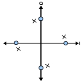
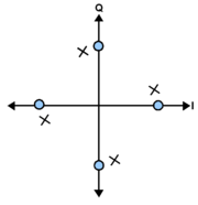
A common form of decision directed carrier recovery begins with quadrature phase correlators producing in-phase and quadrature signals representing a symbol coordinate in the complex plane
. This point should correspond to a location in the modulation constellation diagram
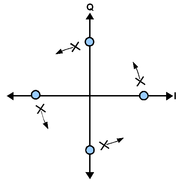
. The phase error between the received value and nearest/decoded symbol is calculated using arc tangent (or an approximation). However, arc tangent, can only compute a phase correction between 0 and . Most QAM constellations also have
  phase symmetry. Both of these shortcomings came be overcome by the use of differential coding
.
In low SNR conditions, the symbol decoder will make errors more frequently. Exclusively using the corner symbols in rectangular constellations or giving them more weight versus lower SNR symbols reduces the impact of low SNR decision errors.
Electronic circuit
An electronic circuit is composed of individual electronic components, such as resistors, transistors, capacitors, inductors and diodes, connected by conductive wires or traces through which electric current can flow...
used to estimate and compensate for frequency and phase differences between a received signal's carrier wave
Carrier wave
In telecommunications, a carrier wave or carrier is a waveform that is modulated with an input signal for the purpose of conveying information. This carrier wave is usually a much higher frequency than the input signal...
and the receiver's local oscillator for the purpose of coherent demodulation
Demodulation
Demodulation is the act of extracting the original information-bearing signal from a modulated carrier wave.A demodulator is an electronic circuit that is used to recover the information content from the modulated carrier wave.These terms are traditionally used in connection with radio receivers,...
.
Carrier system
In telecommunication, a carrier system is a multichannel telecommunications system in which a number of individual channels are multiplexed for transmission...
, a carrier wave is modulated by a baseband
Baseband
In telecommunications and signal processing, baseband is an adjective that describes signals and systems whose range of frequencies is measured from close to 0 hertz to a cut-off frequency, a maximum bandwidth or highest signal frequency; it is sometimes used as a noun for a band of frequencies...
signal. At the receiver the baseband information is extracted from the incoming modulated waveform. In an ideal communications system the carrier frequency
Carrier wave
In telecommunications, a carrier wave or carrier is a waveform that is modulated with an input signal for the purpose of conveying information. This carrier wave is usually a much higher frequency than the input signal...
oscillators of the transmitter and receiver would be perfectly matched in frequency and phase thereby permitting perfect coherent demodulation of the modulated baseband signal. However, transmitters and receivers rarely share the same carrier frequency oscillator. Communications receiver systems are usually independent of transmitting systems and contain their own oscillators with frequency and phase offsets and instabilities. Doppler shift may also contribute to frequency differences in mobile radio frequency
Radio frequency
Radio frequency is a rate of oscillation in the range of about 3 kHz to 300 GHz, which corresponds to the frequency of radio waves, and the alternating currents which carry radio signals...
communications systems. All these frequency and phase variations must be estimated using information in the received signal to reproduce or recover the carrier signal at the receiver and permit coherent demodulation.
Methods
For a quiet carrier or a signal containing a dominant carrier spectral lineSpectral line
A spectral line is a dark or bright line in an otherwise uniform and continuous spectrum, resulting from a deficiency or excess of photons in a narrow frequency range, compared with the nearby frequencies.- Types of line spectra :...
, carrier recovery can be accomplished with a simple band-pass filter at the carrier frequency and/or with a phase-locked loop
Phase-locked loop
A phase-locked loop or phase lock loop is a control system that generates an output signal whose phase is related to the phase of an input "reference" signal. It is an electronic circuit consisting of a variable frequency oscillator and a phase detector...
.
However, many modulation schemes make this simple approach impractical because most signal power is devoted to modulation—where the information is present—and not to the carrier frequency. Reducing the carrier power results in greater transmitter efficiency. Different methods must be employed to recover the carrier in these conditions.
Non-Data-Aided
Non-data-aided/"blind" carrier recovery methods do not rely on any knowledge of the modulation symbols. They are typically used for simple carrier recovery schemes or as the initial method of coarse carrier frequency recovery . Closed-loop non-data-aided systems are frequently maximum likelihood frequency error detectors.Multiply-filter-divide
In this method of non-data-aided carrier recovery a non-linear operation is applied to the modulated signal to create harmonics of the carrier frequency with the modulation removed. The carrier harmonic is then band-pass filterBand-pass filter
A band-pass filter is a device that passes frequencies within a certain range and rejects frequencies outside that range.Optical band-pass filters are of common usage....
ed and frequency divided to recover the carrier frequency. (This may be followed by a PLL.) Multiply-filter-divide is an example of open-loop
Open-loop controller
An open-loop controller, also called a non-feedback controller, is a type of controller that computes its input into a system using only the current state and its model of the system....
carrier recovery, which is favored in burst transactions since the acquisition time is typically shorter than for close-loop synchronizers.
If the phase-offset/delay of the multiply-filter-divide system is known, it can be compensated for to recover the correct phase. In practice, applying this phase compensation is difficult.
In general, the order of the modulation matches the order of the nonlinear operator required to produce a clean carrier harmonic.
As an example, consider a BPSK signal. We can recover the RF carrier frequency,
by squaring:This produces a signal at twice the RF carrier frequency with no phase modulation (modulo
phase is effectively 0 modulation)For a QPSK signal, we can take the fourth power:
Two terms (plus a DC component) are produced. An appropriate filter around
recovers this frequency.Costas Loop
Carrier frequency and phase recovery as well as demodulation can be accomplished using a Costas loopCostas loop
A Costas loop is a phase-locked loop used for carrier phase recovery from suppressed-carrier modulation signals, such as from double-sideband suppressed carrier signals. It was invented by John P. Costas at General Electric in the 1950s...
of the appropriate order. A Costas loop is a cousin of the PLL that uses coherent quadrature signals to measure phase error. This phase error is used to discipline the loop's oscillator. The quadrature signals, once properly aligned/recovered, also successfully demodulate the signal. Costas loop carrier recovery may be used for any M-ary PSK
PSK
PSK may refer to:* Partiya Şoreşa Kürdistan, A Kurdish Separatist guerrilla group in Turkey* Property Solutions Korea, a real estate consulting and development company in South Korea* Phase-shift keying, a digital modulation technique...
modulation scheme. One of the Costas Loop's inherent shortcomings is a 360/M degree phase ambiguity present on the demodulated output.
Decision-Directed
At the start of the carrier recovery process it is possible to achieve symbol synchronization prior to full carrier recovery because symbol timing can be determined without knowledge of the carrier phase or the carrier's minor frequency variation/offset. In decision directed carrier recovery the output of a symbol decoder is fed to a comparison circuit and the phase difference/error between the decoded symbol and the received signal is used to discipline the local oscillator. Decision directed methods are suited to synchronizing frequency differences that are less than the symbol rate because comparisons are performed on symbols at, or near, the symbol rate. Other frequency recovery methods may be necessary to achieve initial frequency acquisition.A common form of decision directed carrier recovery begins with quadrature phase correlators producing in-phase and quadrature signals representing a symbol coordinate in the complex plane
Complex plane
In mathematics, the complex plane or z-plane is a geometric representation of the complex numbers established by the real axis and the orthogonal imaginary axis...
. This point should correspond to a location in the modulation constellation diagram
Constellation diagram
A constellation diagram is a representation of a signal modulated by a digital modulation scheme such as quadrature amplitude modulation or phase-shift keying. It displays the signal as a two-dimensional scatter diagram in the complex plane at symbol sampling instants...
. The phase error between the received value and nearest/decoded symbol is calculated using arc tangent (or an approximation). However, arc tangent, can only compute a phase correction between 0 and
. Most QAM constellations also have phase symmetry. Both of these shortcomings came be overcome by the use of differential codingDifferential coding
In digital communications, differential coding is a technique used to provide unambiguous signal reception when using some types of modulation...
.
In low SNR conditions, the symbol decoder will make errors more frequently. Exclusively using the corner symbols in rectangular constellations or giving them more weight versus lower SNR symbols reduces the impact of low SNR decision errors.