
C-element
Encyclopedia
The Muller C-element, or Muller C-gate, is a commonly used asynchronous logic component originally designed by David E. Muller. It applies logical operations on the inputs and has hysteresis
. The output of the C-element reflects the inputs when the states of all inputs match. The output then remains in this state until the inputs all transition to the other state. This model can be extended to the Asymmetric C-element
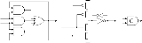
where some inputs only affect the operation in one of the transitions (positive or negative). The figure shows the gate-level and transistor-level implementations and symbol of the C-element.

To understand how this works, look at the transistor-level implementation more closely:

The C-element stores its previous state with two cross-coupled inverters, similar to an SRAM
cell. One of the inverters is weaker than the rest of the circuit, so it can be overpowered by the pull-up and pull-down networks
.
If both inputs are 0, then the pull-up network changes the latch's state, and the C-element outputs a 0. If both inputs are 1, then the pull-down network changes the latch's state, making the C-element output a 1. Otherwise, the input of the latch is not connected to either Vdd or ground, and so the weak inverter (drawn smaller in the diagram) dominates and the latch outputs its previous state.
The Muller C-element was first used in the arithmetic logic unit (ALU) of the ILLIAC II
supercomputer, proposed in 1958, and operational in 1962.
 denotes a "no change" condition.
Hysteresis
Hysteresis is the dependence of a system not just on its current environment but also on its past. This dependence arises because the system can be in more than one internal state. To predict its future evolution, either its internal state or its history must be known. If a given input alternately...
. The output of the C-element reflects the inputs when the states of all inputs match. The output then remains in this state until the inputs all transition to the other state. This model can be extended to the Asymmetric C-element
Asymmetric C-element
Asymmetric C-elements are extended C-elements which allow inputs which only effect the operation of the element when transitioning in one of the directions. Asymmetric inputs are attached to either the minus or plus strips of the symbol. The common inputs which effect both the transitions are...
where some inputs only affect the operation in one of the transitions (positive or negative). The figure shows the gate-level and transistor-level implementations and symbol of the C-element.
To understand how this works, look at the transistor-level implementation more closely:
The C-element stores its previous state with two cross-coupled inverters, similar to an SRAM
Static random access memory
Static random-access memory is a type of semiconductor memory where the word static indicates that, unlike dynamic RAM , it does not need to be periodically refreshed, as SRAM uses bistable latching circuitry to store each bit...
cell. One of the inverters is weaker than the rest of the circuit, so it can be overpowered by the pull-up and pull-down networks
CMOS
Complementary metal–oxide–semiconductor is a technology for constructing integrated circuits. CMOS technology is used in microprocessors, microcontrollers, static RAM, and other digital logic circuits...
.
If both inputs are 0, then the pull-up network changes the latch's state, and the C-element outputs a 0. If both inputs are 1, then the pull-down network changes the latch's state, making the C-element output a 1. Otherwise, the input of the latch is not connected to either Vdd or ground, and so the weak inverter (drawn smaller in the diagram) dominates and the latch outputs its previous state.
The Muller C-element was first used in the arithmetic logic unit (ALU) of the ILLIAC II
ILLIAC II
The ILLIAC II was a revolutionary super-computer built by the University of Illinois that became operational in 1962.-Description:The concept, proposed in 1958, pioneered Emitter-coupled logic circuitry, pipelining, and transistor memory with a design goal of 100x speedup compared to ILLIAC...
supercomputer, proposed in 1958, and operational in 1962.
Truth Table
Here is the truth table for a 2-input c-gate. denotes a "no change" condition.| A B |  |
| 0 0 | 0 |
| 0 1 |  |
| 1 0 |  |
| 1 1 | 1 |