

Apollo spacecraft
Encyclopedia
Project Apollo
The Apollo program was the spaceflight effort carried out by the United States' National Aeronautics and Space Administration , that landed the first humans on Earth's Moon. Conceived during the Presidency of Dwight D. Eisenhower, Apollo began in earnest after President John F...
's goal of landing astronauts on the Moon
Moon
The Moon is Earth's only known natural satellite,There are a number of near-Earth asteroids including 3753 Cruithne that are co-orbital with Earth: their orbits bring them close to Earth for periods of time but then alter in the long term . These are quasi-satellites and not true moons. For more...
by the end of the 1960s
1960s
The 1960s was the decade that started on January 1, 1960, and ended on December 31, 1969. It was the seventh decade of the 20th century.The 1960s term also refers to an era more often called The Sixties, denoting the complex of inter-related cultural and political trends across the globe...
and returning them safely to Earth
Earth
Earth is the third planet from the Sun, and the densest and fifth-largest of the eight planets in the Solar System. It is also the largest of the Solar System's four terrestrial planets...
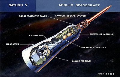
. The spacecraft was made up of (from top to bottom) the Launch Escape System
Launch escape system
A Launch Escape System is a top-mounted rocket connected to the crew module of a crewed spacecraft and used to quickly separate the crew module from the rest of the rocket in case of emergency. Since the escape rockets are above the crew module, an LES typically uses separate nozzles which are...
, the Command Module, the Service Module, and the Lunar Module inside the Spacecraft Lunar Module Adapter. The Command/Service Module combination and the Lunar Module were flown into space using the launch vehicles Saturn IB
Saturn IB
The Saturn IB was an American launch vehicle commissioned by the National Aeronautics and Space Administration for use in the Apollo program...
for eight Earth orbit missions, and the Saturn V
Saturn V
The Saturn V was an American human-rated expendable rocket used by NASA's Apollo and Skylab programs from 1967 until 1973. A multistage liquid-fueled launch vehicle, NASA launched 13 Saturn Vs from the Kennedy Space Center, Florida with no loss of crew or payload...
for three Earth orbital missions and eight lunar missions.
The design was based on the Lunar Orbit Rendezvous
Lunar orbit rendezvous
Lunar orbit rendezvous is a key concept for human landing on the Moon and returning to Earth.In a LOR mission a main spacecraft and a smaller lunar module travel together into lunar orbit. The lunar module then independently descends to the lunar surface. After completion of the mission there, a...
approach: two docked spacecraft
Spacecraft
A spacecraft or spaceship is a craft or machine designed for spaceflight. Spacecraft are used for a variety of purposes, including communications, earth observation, meteorology, navigation, planetary exploration and transportation of humans and cargo....
were sent to the Moon and went into lunar orbit. While one separated and landed, the other remained in orbit. The two craft later rendezvoused and docked in lunar orbit, and one spacecraft returned the crew to Earth.
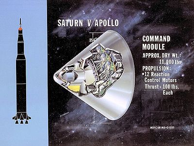
Command Module (CM)
Apollo PGNCS
The Apollo Primary Guidance, Navigation and Control System was a self-contained inertial guidance system that allowed Apollo spacecraft to carry out their missions when communications with Earth were interrupted, either as expected, when the spacecraft were behind the moon, or in case of a...
, communications systems, environmental control system, batteries, heat shield
Heat shield
A heat shield is designed to shield a substance from absorbing excessive heat from an outside source by either dissipating, reflecting or simply absorbing the heat...
, reaction control system, forward docking hatch, side hatch, five windows and the parachute recovery system. It was the only part of the Apollo/Saturn launch vehicle that returned to Earth intact.
Service Module (SM)
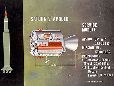
A major portion of the service module was taken up by propellant and the main rocket engine. Capable of multiple restarts, this engine placed the Apollo spacecraft into and out of lunar orbit, and was used for mid-course corrections between the earth and the moon.
The Service Module remained attached to the Command Module throughout the mission. It was jettisoned just prior to reentry into the Earth's atmosphere.
Lunar Module (LM)
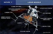
The Descent Stage contained the landing gear, landing radar antenna, descent rocket engine, and fuel to land on the moon. It also had several cargo compartments used to carry among other things, the Apollo Lunar Surface Experiment Packages ALSEP, the Modularized Equipment Transporter (MET) (a hand-pulled equipment cart used on Apollo 14
Apollo 14
Apollo 14 was the eighth manned mission in the American Apollo program, and the third to land on the Moon. It was the last of the "H missions", targeted landings with two-day stays on the Moon with two lunar EVAs, or moonwalks....
), the Lunar Rover
Lunar rover
The Lunar Roving Vehicle or lunar rover was a battery-powered four-wheeled rover used on the Moon in the last three missions of the American Apollo program during 1971 and 1972...
(moon car - Apollo 15
Apollo 15
Apollo 15 was the ninth manned mission in the American Apollo space program, the fourth to land on the Moon and the eighth successful manned mission. It was the first of what were termed "J missions", long duration stays on the Moon with a greater focus on science than had been possible on previous...
, 16
Apollo 16
Young and Duke served as the backup crew for Apollo 13; Mattingly was slated to be the Apollo 13 command module pilot until being pulled from the mission due to his exposure to rubella through Duke.-Backup crew:...
and 17
Apollo 17
Apollo 17 was the eleventh and final manned mission in the American Apollo space program. Launched at 12:33 a.m. EST on December 7, 1972, with a three-member crew consisting of Commander Eugene Cernan, Command Module Pilot Ronald Evans, and Lunar Module Pilot Harrison Schmitt, Apollo 17 remains the...
), surface television camera, surface tools and lunar sample collection boxes.
The Ascent Stage contained the crew cabin, instrument panels, overhead hatch/docking port, forward hatch, optical and electronic guidance systems
Apollo PGNCS
The Apollo Primary Guidance, Navigation and Control System was a self-contained inertial guidance system that allowed Apollo spacecraft to carry out their missions when communications with Earth were interrupted, either as expected, when the spacecraft were behind the moon, or in case of a...
, reaction control system, radar and communications antennas, ascent rocket engine and fuel to return to lunar orbit and rendezvous
Space rendezvous
A space rendezvous is an orbital maneuver during which two spacecraft, one of which is often a space station, arrive at the same orbit and approach to a very close distance . Rendezvous requires a precise match of the orbital velocities of the two spacecraft, allowing them to remain at a constant...
with the Apollo Command and Service Modules.
Launch Escape System (LES)
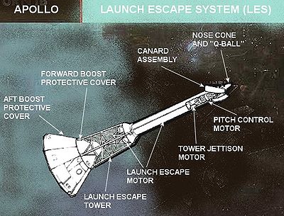

The purpose of the Apollo launch escape system
Launch escape system
A Launch Escape System is a top-mounted rocket connected to the crew module of a crewed spacecraft and used to quickly separate the crew module from the rest of the rocket in case of emergency. Since the escape rockets are above the crew module, an LES typically uses separate nozzles which are...
was to pull the Command Module (which contained the crew cabin) away from the launch vehicle in an abort. The emergency could be a pad fire, exploding launch vehicle or a launch vehicle going off course.
The Launch Escape System would work automatically (or through manual activation) to fire a solid fuel escape rocket and open a canard
Canard (aeronautics)
In aeronautics, canard is an airframe configuration of fixed-wing aircraft in which the forward surface is smaller than the rearward, the former being known as the "canard", while the latter is the main wing...
system to direct the Command Module away from, and off the path of, a launch vehicle in trouble. The Launch Escape System would then jettison and the Command Module would land with its parachute
Parachute
A parachute is a device used to slow the motion of an object through an atmosphere by creating drag, or in the case of ram-air parachutes, aerodynamic lift. Parachutes are usually made out of light, strong cloth, originally silk, now most commonly nylon...
recovery system.
If the emergency happened on the launch pad, the Launch Escape System would lift the Command Module to a sufficient height to allow the recovery parachutes to deploy safely before coming in contact with the ground.
Major components of the Launch Escape System
- Nose Cone and Q-Ball—The nosecone of the LES contained a pitot-static systemPitot-static systemA pitot-static system is a system of pressure-sensitive instruments that is most often used in aviation to determine an aircraft's airspeed, Mach number, altitude, and altitude trend. A pitot-static system generally consists of a pitot tube, a static port, and the pitot-static instruments...
to sense the dynamic pressure ("Q") of the air, and thereby determine the airspeedAirspeedAirspeed is the speed of an aircraft relative to the air. Among the common conventions for qualifying airspeed are: indicated airspeed , calibrated airspeed , true airspeed , equivalent airspeed and density airspeed....
of the space vehicle during flight through the atmosphere. This structure, known as the Q-ball, relayed this information to the command module and the launch vehicle guidance system. - Q-Ball cover—The Q-ball's pitot-static ports, which could easily be clogged by debris, were protected by a styrofoam cover that was removed a few seconds before launch. The Q-ball cover was split in half vertically and held together by a 2 inches (50.8 mm) rubber band. A razor blade was positioned behind the rubber band, pinched between the halves of the cover. A wire rope was connected to the top and bottom of the razor blade and to both halves of the cover. The wire rope was routed through a pulley on the hammerhead crane at the top of the launch umbilical tower (LUT) down to a tube on the right side of the 360 feet (109.7 m) level of the LUT. The wire rope was connected to a cylindrical weight inside a tube. The weight rested on a lever controlled by a pneumatic solenoid valve. When the valve was actuated from the Launch Control Center (LCC), the pneumatic pressure of 600 PSI GN2 (nitrogen gas) rotated the lever down allowing the weight to drop down the tube. The dropping weight pulled the wire rope, which pulled the blade cutting the rubber band, and the wire rope pulled the halves of the cover away from the launch vehicle. The apparent overengineering of this simple system was due to the fact that the launch escape system, which depended on the Q-ball data, was armed 5 minutes before launch, so retraction of the Q-ball cover was a life-critical part of a possible pad abort.
- Canard Assembly and Pitch Motor—These worked in combination to direct the Command Module off a straight path and to the side during an emergency. This would direct the Command Module off the flight path of an exploding launch vehicle. It would also direct the Command Module to land off to the side of any launch pad fire and not in the middle of it.
- Tower Jettison Motor—A smaller solid fuel motor that jettisons the Launch Escape System after it is no longer needed. This usually happens after second stage ignition.
- Launch Escape Motor—The main solid fuel rocket motor that, firing through four rocket nozzles, pulls the Command Module rapidly away from a launch emergency.
- Launch Escape Tower—Assembly that attaches the Launch Escape System rocket motors to the Command Module.
- Boost Protective Cover—Hollow conical structure that fit over the Command Module during launch. It protected the Command Module heat shield and windows during ascent through the atmosphere. It also protected the Command Module from rocket exhaust should the Launch Escape System have to be used.
Specifications
- Length minus BPC: 32 ft 6 in (9.92 m)
- Length with BPC: 39 ft 5 in (12.02 m)
- Diameter: 2 ft 2 in (0.66 m)
- Total mass: 9200 pounds (4,173 kg)
- ThrustThrustThrust is a reaction force described quantitatively by Newton's second and third laws. When a system expels or accelerates mass in one direction the accelerated mass will cause a force of equal magnitude but opposite direction on that system....
, 36,000 ft: 147000 pound-forces (653.9 kN) - Thrust, maximum: 200000 pound-forces (889.6 kN)
- Burn time: 4.0 seconds
Abort tests
- Pad Abort Test-1Pad Abort Test-1 (Apollo)Pad Abort Test 1 was the first abort test of the Apollo spacecraft on November 7, 1963.-Objectives:Pad Abort Test 1 was a mission to investigate the effects on the Apollo spacecraft during an abort from the pad. The launch escape system had to be capable of pulling the spacecraft away from a...
—Launch Escape System (LES) abort test from launch pad with Apollo Boilerplate BP-6. - Pad Abort Test-2Pad Abort Test-2 (Apollo)Pad Abort Test 2 was the follow-on second abort test to Pad Abort Test 1 of the Apollo spacecraft.-Objectives:Apollo Pad Abort Test 2 was the fifth of six unmanned Apollo missions that flight tested the capability of the launch escape system to provide for safe recovery of Apollo crews under...
—LES pad abort test of near Block-I CM with Apollo Boilerplate B-23A. - Little Joe IILittle Joe IILittle Joe II was an American space launch vehicle used for five unmanned tests of the launch escape system and to verify the performance of the command module parachutes for the Apollo spacecraft from 1963–66...
—In-air LES abort tests.
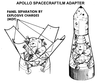
Spacecraft Lunar Module Adapter (SLA)
S-IVB
The S-IVB was built by the Douglas Aircraft Company and served as the third stage on the Saturn V and second stage on the Saturn IB. It had one J-2 engine...
rocket stage. It protected the Lunar Module (LM), the Service Propulsion System engine nozzle, and the launch vehicle to Service Module umbilical during launch and ascent through the atmosphere.
The SLA was composed of four fixed 7 feet (2.1 m) panels bolted to the Instrument Unit
Saturn V Instrument Unit
The Saturn V Instrument Unit is a ring-shaped structure fitted to the top of the Saturn V rocket's third stage and the Saturn IB's second stage . It was immediately below the SLA panels that contained the Lunar Module. The Instrument Unit contains the guidance system for the Saturn V rocket...
on top of the S-IVB
S-IVB
The S-IVB was built by the Douglas Aircraft Company and served as the third stage on the Saturn V and second stage on the Saturn IB. It had one J-2 engine...
stage, which were connected via hinges to four 21 feet (6.4 m) panels which would open from the top similar to flower petals.
The SLA was made from 1.7 inches (43.2 mm) thick aluminum honeycomb material. The exterior of the SLA was covered by a thin (0.03 –) layer of cork and painted white to minimize thermal stresses during launch and ascent.
The Service Module was bolted to a flange at the top of the longer panels, and power to the SLA multiply redundant pyrotechnics was provided by an umbilical. Because a failure to separate from the S-IVB
S-IVB
The S-IVB was built by the Douglas Aircraft Company and served as the third stage on the Saturn V and second stage on the Saturn IB. It had one J-2 engine...
stage could leave the crew stranded in orbit, the separation system used multiple signal paths, multiple detonators and multiple explosive charges where the detonation of one charge would set off another even if the detonator on that charge failed to function.
Once in space, the astronauts pressed the 'CSM/LV Sep' button on the control panel to separate the Command and Service Module (CSM) from the launch vehicle. Detonating cord
Detonating cord
Detonating cord is a thin, flexible plastic tube filled with PETN . With the PETN exploding at a rate of approximately 4 miles per second, any common length of det cord appears to explode instantaneously...
was ignited around the flange between the Service Module and SLA, and along the joints between the four SLA panels, releasing the Service Module and blowing apart the connections between the panels. Dual-redundant pyrotechnic thrusters at the lower end of the SLA panels then fired to rotate them around the hinges at 30-60 degrees per second.
On the Apollo 7 flight the SLA panels were retained on the S-IVB
S-IVB
The S-IVB was built by the Douglas Aircraft Company and served as the third stage on the Saturn V and second stage on the Saturn IB. It had one J-2 engine...
, but concerns about collision between the CSM and the SLA panels when docking with the Lunar Module led to a decision that the Saturn V launches would release the panels during the separation process. When they opened to an angle of approximately 45 degrees the hinges connecting the moving panels to the fixed panels disengaged, and springs pushed the panels away from the S-IVB
S-IVB
The S-IVB was built by the Douglas Aircraft Company and served as the third stage on the Saturn V and second stage on the Saturn IB. It had one J-2 engine...
at a velocity of around five miles per hour. Hence by the time the astronauts had rotated the Command/Service Module through one hundred and eighty degrees in preparation for docking
Space rendezvous
A space rendezvous is an orbital maneuver during which two spacecraft, one of which is often a space station, arrive at the same orbit and approach to a very close distance . Rendezvous requires a precise match of the orbital velocities of the two spacecraft, allowing them to remain at a constant...
, the panels were a safe distance away with no chance of a collision occurring.
The Lunar Module was connected to the SLA at four points around the lower panels. After the astronauts docked the CSM to the LM, they blew charges to separate those connections and a guillotine severed the LM to Instrument Unit
Saturn V Instrument Unit
The Saturn V Instrument Unit is a ring-shaped structure fitted to the top of the Saturn V rocket's third stage and the Saturn IB's second stage . It was immediately below the SLA panels that contained the Lunar Module. The Instrument Unit contains the guidance system for the Saturn V rocket...
umbilical. After the charges fired, springs pushed the LM away from the S-IVB
S-IVB
The S-IVB was built by the Douglas Aircraft Company and served as the third stage on the Saturn V and second stage on the Saturn IB. It had one J-2 engine...
and the astronauts were free to continue their trip to the Moon.
Specifications
- Height: 28 ft (8.5 m)
- Apex Diameter: 12 ft 10 in (3.9 m) Service Module end
- Base Diameter: 21 ft 8 in (6.6 m) S-IVB end
- Weight: 4050 lb (1,837 kg)
- Volume: 6700 ft3, 4900 ft3 usable
Abort modes
- Apollo abort modesApollo abort modesDuring the launch of an Apollo spacecraft by the Saturn V rocket, the flight could be aborted to rescue the crew if the rocket failed catastrophically. Depending on how far into the flight the crew were, they would use different procedures or modes...
- Pad Abort Test-1Pad Abort Test-1 (Apollo)Pad Abort Test 1 was the first abort test of the Apollo spacecraft on November 7, 1963.-Objectives:Pad Abort Test 1 was a mission to investigate the effects on the Apollo spacecraft during an abort from the pad. The launch escape system had to be capable of pulling the spacecraft away from a...
- Launch Escape System (LES) abort test from launch pad with Apollo Boilerplate BP-6. - Pad Abort Test-2Pad Abort Test-2 (Apollo)Pad Abort Test 2 was the follow-on second abort test to Pad Abort Test 1 of the Apollo spacecraft.-Objectives:Apollo Pad Abort Test 2 was the fifth of six unmanned Apollo missions that flight tested the capability of the launch escape system to provide for safe recovery of Apollo crews under...
- LES pad abort test of near Block-I CM with Apollo Boilerplate B-23A.
Current locations of spacecraft
The disposition of all Command Modules, and all unflown Service Modules is listed at Apollo Command/Service Module#CSMs produced. (All flown Service Modules burned up in the Earth's atmosphere at termination of the missions.)The disposition of all Lunar Modules is listed at Apollo Lunar Module#Lunar Modules produced.
External links
- NASA report JSC-03600 Apollo/Skylab ASTP and Shuttle Orbiter Major End Items, Final Report, March 1978; NASA report listing dispositions of all rockets and spacecraft used in the Apollo, Skylab, Apollo-Soyez Test Project and early shuttle missions, as of 1978.